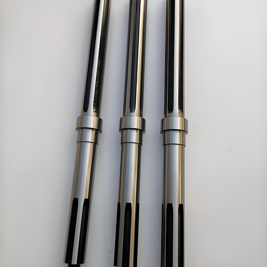
Shafts are round cross-section rotating machine parts that transfer power between components or from drive units to driven equipment. One end connects to the power source, the other links to the machine for power transmission.
Shafts can be solid or hollow as required; hollow shafts help reduce weight and offer structural advantages. As one of the most critical elements in machinery, shafts support rotating parts such as pulleys and gears. They are mounted on bearings within rigid machine housings, and gears and pulleys fitted onto the shaft enable the transmission of motion.
Rotating elements are mounted on the shaft via keys. The shaft bears bending moment and torque caused by reaction forces from supported components and power transmission.
Shafts can be classified into the following three types according to load conditions:
- Mandrel: A shaft that bears only bending moment without transmitting torque. Mandrels are further divided into rotating mandrels and stationary mandrels.
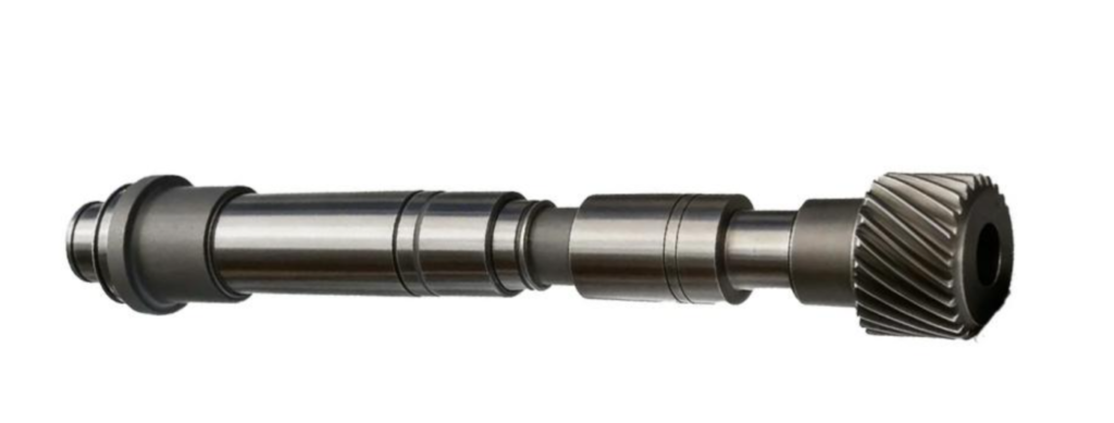
- Shaft / Driving Shaft: A shaft subjected to both bending moment and torque, such as shafts used in gear reducers.
- Transmission Shaft: A shaft that only transmits torque with no significant or negligible bending moment. A typical example is the driveshaft connecting the gearbox and rear axle in automobiles.
Machining Precision of Shafts
The surfaces of shaft parts are generally divided into support journals and fitting journals.
The outer circular journals fitted with bearing inner rings are support journals, which locate and support the shaft. They require high dimensional tolerance grades, usually IT5~IT7.
Journals mated with various transmission components are fitting journals, with relatively lower tolerance grades, commonly IT6~IT9.
Form precision mainly refers to the roundness and cylindricity of critical surfaces such as journal surfaces, outer conical surfaces and tapered bores. Their errors shall generally be limited within the dimensional tolerance range. For precision shafts, additional geometric form precision shall be specified separately on the engineering drawing.
Positional accuracy includes the concentricity of internal and external surfaces as well as critical shaft surfaces, radial runout of circular surfaces, perpendicularity of key end faces to the shaft centerline, and parallelism between end faces.
All machined surfaces of shafts have surface roughness requirements, which are generally determined based on machining feasibility and cost efficiency.
The surface roughness of support journals is typically Ra 0.2~1.6 μm, while that of journals mating with transmission components is Ra 0.4~3.2 μm.
Shaft Materials and Selection
Shafts are mainly made of carbon steel and alloy steel.
The most commonly used carbon steel is 45steel, which is generally normalized or quenched and tempered to improve its mechanical properties.
Compared with carbon steel, alloy steel delivers better mechanical performance and heat treatment characteristics. However, it is more sensitive to stress concentration and higher in cost. Therefore, alloy steel is mostly used for working conditions requiring high speed, heavy load, wear resistance, high-temperature or low-temperature resistance and other special requirements.
At room temperature, the difference in elastic modulus between alloy steel and carbon steel is very small. Replacing carbon steel with alloy steel cannot significantly improve the stiffness of the shaft.
Shafts subjected to heavy loads and requiring high strength, compact structure or good wear resistance can be made of alloy steel. Commonly used grades include 40Cr, 20Cr, 35SiMn, etc.
With the same dimensions, the use of alloy steel cannot increase shaft stiffness, as the elastic modulus of various steels is generally similar. Alloy steel is more sensitive to stress concentration, so the structural design of the shaft must minimize stress concentration effects. When alloy steel is adopted, corresponding heat treatment is mandatory to fully exert the material’s performance advantages.
Shaft blanks are generally made of hot-rolled round steel or forgings. For shafts with complex shapes such as crankshafts and camshafts, cast steel or ductile iron can also be used. Ductile iron features good vibration damping, low sensitivity to stress concentration, and cost advantages.
Heat Treatment of Shaft Parts
Medium carbon steel and medium carbon alloy steel mainly adopt rolled or forged grades including 35, 40, 45, 50, 40Cr, 40CrNi and 40MnB. These materials are generally subjected to normalizing or quenching and tempering heat treatment.
For journals with high wear resistance requirements, surface quenching is applied locally at the journal positions. Material selection shall be determined according to load type, part dimensions and hardenability of the steel.
For shafts under bending and torsional loads, stress decreases gradually from the surface to the core, so high hardenability of the steel is not required. For shafts under tensile and compressive loads, stress is uniformly distributed over the shaft cross-section, and steel with high hardenability should be selected.
When shafts are subjected to heavy impact loads, demanding high strength and toughness, or requiring further improvement in journal wear resistance, carburizing alloy steels such as 20Cr and 20CrMnTi are selected, followed by carburizing, quenching and low-temperature tempering treatment.For lightly loaded and non-critical shafts, ordinary carbon steels such as Q235 to Q275 can be adopted.
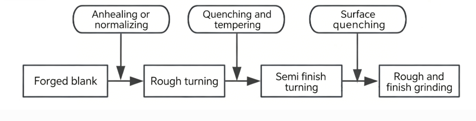
The machining of general shaft parts can be divided into three stages: rough turning, semi-finish turning, and rough/finish grinding. The heat treatment processes for each stage are arranged as follows:
Normalizing or Annealing
All forged blanks require normalizing or annealing prior to machining. This refines the internal grain structure of the steel, relieves forging residual stress, reduces material hardness, and improves cutting machinability.
Quenching and Tempering
Quenching and tempering is generally arranged after rough turning and before semi-finish turning, to achieve excellent comprehensive mechanical properties.
Surface Quenching
Surface quenching is usually performed before finish machining, so as to correct local deformation caused by quenching.
Low-temperature Aging Treatment
For shafts with high precision requirements, low-temperature aging treatment is additionally required after local quenching or rough grinding.
Selection of Positioning Datum for Shaft Parts
The most commonly used positioning datum for general shaft parts is two center holes.
The main items of positional accuracy for shaft parts include the concentricity of all outer circular and threaded surfaces, as well as the perpendicularity of end faces to the shaft axis. The design datum for these surfaces is generally the shaft centerline. Positioning with two center holes complies with the datum coincidence principle. Since center holes are adopted as the positioning datum in most working procedures, multiple outer circles and end faces can be machined in a unified reference.
The two center holes cannot be used as positioning datums under the following conditions:
When rough turning the outer circle, to improve workpiece rigidity, the shaft’s outer cylindrical surface is used as the positioning datum, or the outer circle and center holes are adopted as the combined positioning datum.
For hollow shaft parts with through holes, the original center holes for positioning will disappear after hole machining. To still use center holes as the positioning datum after through-hole processing, the commonly adopted methods are as follows:
| When the diameter of the central through hole is small, a 60° inner conical surface with a width no more than 2 mm can be chamfered directly at the hole mouth to replace the center hole. |
| For shafts with cylindrical holes, tapered plugs with a taper of 1:500 can be used. If the taper of the shaft hole is small, the taper of the tapered plug shall be identical to that of the positioning holes at both ends of the workpiece. |
| If the shaft hole is a tapered hole with a large taper, a mandrel fitted with a tapered plug may be adopted. |
Machining Process Route of Shafts
The main surfaces of shaft parts are the outer cylindrical surfaces of each journal. For hollow shafts, the precision of inner holes is generally not high, while secondary surfaces such as threads, splines and keyways on precision spindles also require relatively high precision.
The machining process route of shaft parts mainly focuses on the machining sequence of outer circles, with the machining of secondary surfaces reasonably inserted into the process.
The following are the commonly adopted machining process routes for shaft parts of different precision grades and materials in actual production:
Process route for shaft parts made of carburizing steel
Material preparation → Forging → Normalizing → Center hole drilling → Rough turning → Semi-finish turning & finish turning → Carburizing (or carbonitriding) → Quenching & low-temperature tempering → Rough grinding → Machining of secondary surfaces → Finish grinding
Process route for shaft parts made of precision quenched and tempered steel
Material preparation → Forging → Normalizing (Annealing) → Center hole drilling → Rough turning → Quenching and tempering → Semi-finish turning & finish turning → Surface quenching & tempering → Rough grinding → Machining of secondary surfaces → Finish grinding
Process route for shaft parts made of nitriding steel
Material preparation → Forging → Normalizing (Annealing) → Center hole drilling → Rough turning → Quenching and tempering → Semi-finish turning & finish turning → Low-temperature aging → Rough grinding → Nitriding treatment → Machining of secondary surfaces → Finish grinding → Lapping grinding
Process route for overall quenched shaft parts
Material preparation → Forging → Normalizing (Annealing) → Center hole drilling → Rough turning → Quenching and tempering → Semi-finish turning & finish turning → Machining of secondary surfaces → Overall quenching → Rough grinding → Low-temperature aging → Finish grinding
Machining Process Example of Shaft Parts
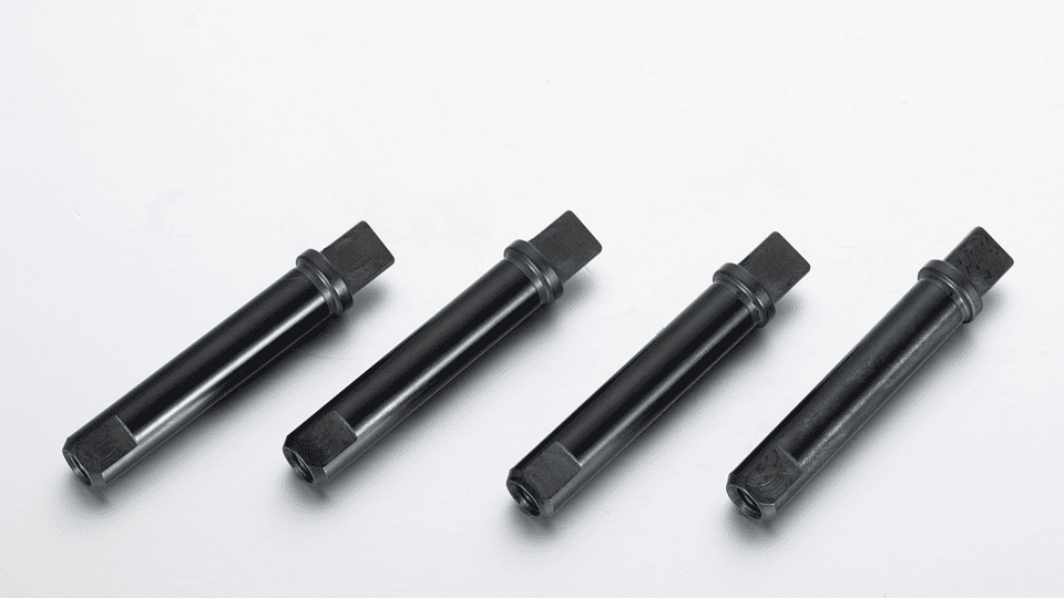
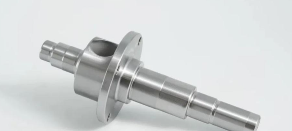
The figure below shows a shaft part. This paper introduces the machining process of the shaft in small-batch production.
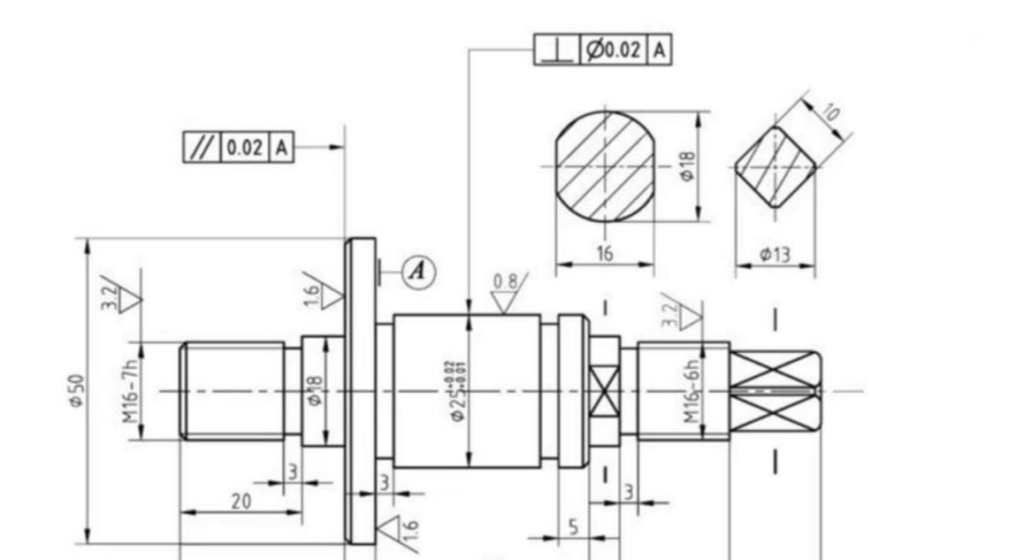
This is a stepped shaft composed of cylindrical surfaces, shaft shoulders, threads, square sections and other features.
Material and blank preparation
The shaft is made of 45steel. Although it is produced in small batches, the journal dimensions vary greatly, with a maximum diameter of ø50 mm and a minimum of ø13 mm. To save raw materials, a forging is adopted as the blank, and the forging is subjected to normalizing treatment.
Main Technical Requirements
The dimensional accuracy of the ø25 mm journal of the shaft is IT7 grade, with a surface roughness of Ra 0.8 μm.
Taking the φ50 mm shaft shoulder as the datum, the perpendicularity tolerance of the φ25 mm axis is 0.02 mm, and the parallelism tolerance between the two end faces of the shaft shoulder is 0.02 mm.
Selection of Positioning Datum
To guarantee the concentricity of each journal, the refined datum adopts positioning with center holes at both ends. The positioning datum remains unchanged in turning, milling and grinding processes.
Determination of Machining Methods for Main Surfaces
Most surfaces of the shaft are rotary surfaces, which are mainly formed by turning and grinding. Since the φ25 mm journal and both side faces of the φ50 mm shaft shoulder have strict geometric tolerance requirements in addition to dimensional accuracy, grinding is required after turning.
The machining scheme for outer circular surfaces is: rough turning → semi-finish turning → grinding.
Machining Stages
For parts with high precision requirements, roughing and finishing shall be separated to ensure machining quality. The machining of this shaft is divided into three stages: rough turning, semi-finish turning and grinding.
Heat Treatment
Hardening by surface quenching is required for the φ25 mm×35 mm section and the square head of the shaft. The heat treatment is arranged after semi-finishing and before grinding.
Normalizing is carried out after blank manufacturing to eliminate internal stress, refine grain structure and improve cutting machinability.
The process route of the shaft is as follows: Forging → Normalizing → Facing and center hole drilling → Turning all outer circles → Semi-finish turning of outer circles, groove turning and side face machining → Thread turning → Square milling → Surface quenching → Grinding → Inspection.
About Us
Zorapid specializes in customized manufacturing of non-standard parts. Our manufacturing services cover CNC machining, sheet metal fabrication, aluminum profile processing and more. From conceptual design to functional prototypes, from one-off sampling to small-batch production of up to 5,000 pieces, we rely on our in-house quality factory and partnered production capacity to support your agile development, enabling order today, test the day after tomorrow at the fastest speed.
Core Key Points of Machining Precision for Shaft Parts
Process Chain and Precision Control
This process follows a typical alternating mode of heat treatment and mechanical machining. Each heat treatment procedure is matched with subsequent precision compensation operations:
- Annealing / Normalizing: Relieve forging residual stress, improve machinability, and lay a foundation for rough machining.
- Quenching and Tempering: Enhance the core strength and toughness; meanwhile, slight deformation occurs, which needs to be corrected by semi-finish turning.
- Surface Quenching: Increase surface hardness accompanied by tiny deformation, which is finally finished to the required dimensions and geometric tolerances through rough and precision grinding.
Key Factors Affecting Precision
- Clamping Error: Repeated clamping (from turning to grinding) introduces concentricity errors. Five-axis machining or one-time clamping process can significantly reduce such problems.
- Thermal Deformation: Temperature changes during heat treatment and cutting are the main causes of shaft part deformation.
- Surface Roughness: The grinding process is critical to meeting precision requirements such as Ra≤1.6μm, which directly affects the sealing and wear resistance of mating surfaces.
FAQ
How to choose the right material for a shaft?
Balance load capacity, wear resistance, corrosion resistance, and cost. For example, use 40Cr for high torque, stainless steel for corrosive environments, and aluminum for low-load, weight-sensitive parts.
What causes common precision errors?
Multiple clamping setups, tool deflection, thermal expansion, and post-heat treatment distortion. 5-axis machining or one-setup turning/milling reduces these errors.
What heat treatments are standard for shafts?
Annealing/normalizing (stress relief, improved machinability), quenching + tempering (core strength, toughness), and surface hardening (induction hardening, carburizing, nitriding for wear resistance).
Why are machining and heat treatment steps interleaved?
To relieve stresses and correct distortion at each stage. Rough machining removes most material before hardening, and final grinding achieves tight tolerances.