Looking around the world, technology is ubiquitous, ranging from ordinary chairs to space stations. Since the invention of the wheel, shafts have been in constant use by humanity. They are regarded as the backbone of all machinery.
The function of a shaft is to transmit torque, momentum and motion to connected components. There is a wide variety of shaft types, among which spline shafts stand out, along with their subdivided categories and diverse manufacturing materials.
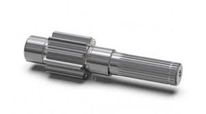
What Is a Spline Shaft? Definition and Core Mechanics
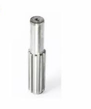
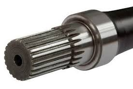
A spline shaft is a core component of machinery. Its mating section consists of grooved ridges. It facilitates torque transmission and alignment of machine parts. By distributing loads evenly, these shafts help equipment avoid wear and slippage.
Spline Shaft vs. Key Shaft: Which One to Use and When
The criteria for choosing between a spline shaft and a key shaft are straightforward.
For applications requiring high precision and torque control, spline shafts are the optimal choice.
Key shafts are suitable for scenarios with low torque demand and high cost-effectiveness requirements.
Torque Capacity Comparison
Component design determines its torque-bearing capability.
Conventional tests such as shear load and fatigue tests show that the torque capacity of spline shafts can easily be 30% higher than that of key shafts.
Alignment Precision
Backlash in robotic and CNC equipment causes alignment accuracy issues.
Spline shafts eliminate backlash and maintain precise alignment during operation.
What is the definition of a spline shaft?
Key parameters include:
Tooth profile: Involute
Root diameter
Pressure angle: 30°, mainly for industrial applications
5 Key Functions of Spline Shafts in Modern Machinery
Spline shafts serve as the backbone of modern machinery. They feature the following critical functions:
1. Slip-Free Torque Transmission
As mentioned earlier, spline shafts efficiently transfer power to connected wheels and are widely applied in automotive transmission systems.
2. Axial Motion Adjustment
Linear actuators mainly rely on spline shafts to maintain accurate alignment during movement.
3. Vibration Damping by Load Distribution
Spline shafts enable even load distribution, which helps reduce vibration.
4. Precision Alignment for CNC Equipment
CNC operations run at high speeds. Spline shafts maintain tight tolerances and deliver precise alignment.
5. Fail-Safe Disengagement
Spline shafts disengage under overload conditions to protect the entire mechanical system.
Types of Spline Shafts: A Designer’s Selection Guide
The choice of spline shaft type ultimately depends on application requirements, load type, operating speed and other working conditions.
Involute Splines (DIN 5480 / ISO 4156)
The international standard ISO 4156 and European standard DIN 5480 both specify regulations for involute spline shafts.
In industrial applications, involute splines are the most widely used shaft type due to the following features:
- Self-centering
- 30° pressure angle
- Gradual load transfer
Applications
Automotive gearboxes
Industrial gearboxes
Aerospace actuators
Why 30° Pressure Angle Is Ideal for Industrial Applications
The 30° pressure angle is suitable for 80% of industrial applications. It achieves an optimal balance between load capacity and fatigue life.
Straight Splines (SAE J498)
Straight splines feature a simple structure and are easy to manufacture. They have a flat tooth profile on the surface, with relatively low load distribution efficiency.
Properties
- RPM limit: Optimal below 500
- Flat tooth sides
- Lower cost
Applications
Agricultural industry (tractor shafts)
Hydraulic pumps
Legacy industrial equipment
Low-cost alternative for applications below 500 RPM
Speed below 500 RPM represents medium rotational speed and torque. For operation under such conditions, straight-sided splines are the optimal and cost-effective choice.
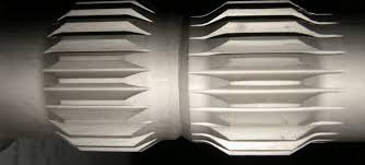
Serrated Splines (Military Standard MIL-S-8879)
Serrated splines feature 45° angled teeth, which enable them to withstand axial impact loads, extreme vibration and high misalignment conditions.
Typical Applications of Serrated Splines
Black Hawk helicopter rotor shafts
Missile launch rail actuators
45° serrated teeth, suitable for military-grade axial loads
Engineered specifically to handle extreme axial loads in helicopter rotor systems.
Ball Splines
Ball splines offer the following advantages for linear motion systems:
- Hardened rolling elements deliver nearly zero backlash
- 90% less friction compared with keyed shafts
- 10 times longer service life in high-cycle applications
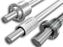
Applications
Semiconductor wafer processors
Medical robots
6-axis CNC trunnion tables
Crown Splines: Misalignment Compensation
Crown splines feature a barrel-shaped profile with a controlled crown radius, which helps:
- Self-compensate for angular misalignment
- Achieve uniform load distribution
- Extend service life by up to 300%
Applications
Wind turbine gearboxes
Marine propulsion shafts
Mining conveyor drive units
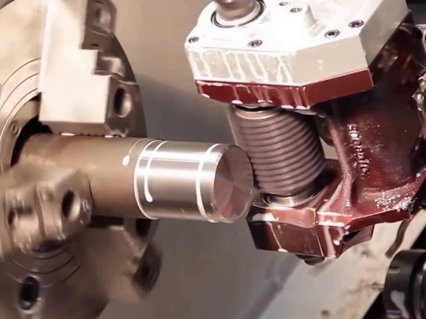
How to Manufacture a Spline Shaft – Step-by-Step Guide
Learn step by step how to precisely manufacture a spline shaft:
Step 1: Design Validation and Tolerance Mapping
Key tasks performed in this step:
3D FEA simulation – Verify stress distribution under maximum torque using ANSYS software
Tolerance stack-up analysis – ISO 4156 Class 5 for thermal expansion calculation
Spline profile selection – Involute DIN 5480 and straight tooth SAE J498
Tools:
Gear design software (KISSsoft, Romax)
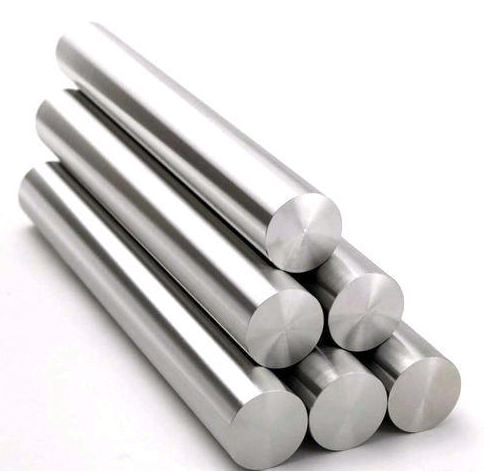
Step 2: Material Preparation & Pre-Machining
Material preparation includes multiple processes:
Material Cutting
Cut bar stock with a cutting machine.
Turning
Perform turning on a lathe; CNC machines can be adopted for higher-precision turning.
- Diameter tolerance: ±0.05 mm
- Surface finish: 3.2 μm microscopic roughness
- Drilling: Precision center hole machining
Annealing is recommended to relieve internal stress and prevent deformation.
Step 3: Main Spline Forming
Core operations for spline forming:
Broaching Machine
Adopt tungsten carbide broaches with a broaching speed of 5–15 m/min.
Broaching complies with DIN 1415 standard, achieving DIN Grade 7 precision.
Gear Hobbing Machine
CNC gear hobbing machines are applied.
Tools: HCC Furnace
Tolerance Grade: AGMA Class 10 tolerance can be achieved
Grinding
Applied when shaft hardening is required
Thread grinding machine with CBN grinding wheel
Achieves a surface finish of 0.4 μm
Step 4: Post-Processing and Surface Enhancement
Machining operations leave residual blemishes and cannot deliver the required surface quality of finished parts, so post-processing is always essential.
Common post-processing techniques include:
Heat Treatment
To achieve targeted surface hardening
Shot Peening
To improve fatigue life
Coating
DLC coating is commonly applied to reduce wear
Step 5: Quality Assurance and Testing
Inspection Protocols:
Standard testing protocols for spline shafts are as follows:
- CMM Measurement – Tooth profile accuracy (±0.005 mm)
- Gear Rolling Tester – Check composite error per DIN 3961
- Torque Testing – Verify 30% higher capacity compared with keyed shafts
Certifications:
Spline shafts must comply with the following certifications:
- ISO 9001 process validation
- PPAP documentation for automotive customers
What Are the Common Spline Shaft Standards? – SAE, DIN, ISO
Standards act as guidelines for engineers, covering material selection, manufacturing techniques, post‑processing methods, and more. They promote compatibility and consistent performance across industries.
SAE J500 (Automotive) vs. DIN 5480 (EU Machinery)
SAE J500 is the standard for automotive applications, commonly used with stainless steel.
DIN 5480 is intended for mechanical power transmission.
Tooth Thickness Tolerances
Different standards specify different tolerance values:
- SAE: ±0.0002 inches
- DIN Class 5: ±0.05 mm
Metric vs. Imperial Splines
North America uses imperial splines, while metric splines are dominant worldwide.
How to Read a Spline Code
Using “48x3x30° DIN 5482” as an example:
- 48 teeth
- 3 mm module
- 30° pressure angle
Spline Shaft Material Selection: From Aluminum Alloys to Superalloys
The material selection of spline shafts directly affects their service performance in applications. Splines are selected and applied according to actual working conditions.
General Industrial Applications
Below are the advantages and disadvantages of commonly used spline shaft materials, which cover 80% of general industrial scenarios.
Alloy Steel (4140 / 4340)
4140 and 4340 are medium and low carbon alloy steels. Most spline shafts are manufactured from these alloys.
Pros
High strength, high toughness, and cost-effectiveness.
Cons
Without chromium in its composition, it is highly susceptible to corrosion.
Stainless Steel (17-4PH)
PH stands for precipitation hardening. This martensitic stainless steel is known for its optimal mechanical properties.
Pros
- High strength
- Excellent corrosion resistance, even in chloride-rich salt environments
- Good weldability
Cons
- Difficult to machine, resulting in high cost
- Limited high-temperature performance
Lightweight Applications
The following materials are used in fields where lightweight design is critical, such as aerospace and automotive industries.
Aerospace-Grade Aluminum (7075-T6)
This alloy is specially produced for the aerospace industry using artificial aging treatment, delivering enhanced mechanical properties.
Pros
- 60% lighter than steel
- High strength-to-weight ratio
- Good corrosion resistance
Cons
- Lower fatigue limit compared to steel
Titanium Alloy (Ti-6Al-4V)
Aluminum and vanadium are the main alloying elements, making it suitable for aerospace, medical implants, and high-performance engineering applications.
Pros
- High strength
- Light weight
- Excellent biocompatibility
- Outstanding structural rigidity
Cons
- Poor wear resistance
- Risk of hydrogen embrittlement
- Tendency to gall and seize
Extreme Conditions (High Temperature / Corrosion)
Oxidation and corrosion are major challenges in extreme environments such as high-temperature or high-salt conditions. The following materials perform exceptionally well:
Nickel-Based Superalloy (Inconel 718)
With high nickel and chromium content, it offers outstanding mechanical properties. Applications include aerospace, marine, and power generation.
Pros
- Excellent performance at high temperatures
- Superior corrosion resistance
- Good fatigue and creep resistance
Cons
- Prone to segregation in large castings
- High cost due to expensive alloying elements
Cobalt-Chromium Alloy (Hastelloy C276)
High amounts of molybdenum and chromium, plus small amounts of cobalt, make this alloy ideal for harsh conditions.
Pros
- Exceptional corrosion resistance
- High-temperature strength
- Non-magnetic properties
Cons
- Limited supply and supply chain issues
- Very difficult to machine
Spline Shaft Design: 4 Rules to Prevent Failure
By following these rules, you can avoid failures in practical applications.
Tip 1: Prevent Tooth Breakage with AGMA Stress Calculation
Apply AGMA stress calculation to avoid spline tooth fracture failure. Two key indicators are calculated in the analysis:
- Tooth root bending stress
- Flank contact stress
Tip 2: Set Fillet Radius to 0.25 × Module to Prevent Cracks
Design the fillet radius at 0.25 × module. A properly optimized fillet can extend service life by up to 400 times.
Tip 3: Adopt Ra 0.8 μm Surface Finish to Extend Fatigue Life
Use grinding process to achieve a surface roughness of Ra 0.8 μm. Poor surface finish will compromise durability and lead to fatigue failure.
Tip 4: Machine 45° Helical Grooves to Reduce Wear by 60%
Machining 45° helical grooves effectively reduces adhesive wear. Such grooves are critical for automotive gearboxes and hydraulic pumps.
Spline Shaft Applications: Industry-Specific Solutions
This section covers typical applications of spline shafts.
Automotive: 24-Spline vs. 26-Spline Input Shafts
The 26-spline shaft can withstand up to 650 Nm of torque, while the 24-spline shaft is a lower-cost option, most suitable for older designs.
Aerospace: Self-Lubricating Splines in Jet Engines
Self-lubricating spline shafts are used to eliminate grease contamination in fan blade pitch systems operating from -60°C to 300°C.
Robotics: Polymer-Coated Splines for Quiet Operation
For silent operation, robotic spline shafts are coated with PEEK. These coatings also improve corrosion resistance.
Spline Shaft Maintenance and Repair Techniques
Learn how to maintain and repair spline shafts.
Regrooving: When to Regroove or Replace
When to regroove
- Minor wear
- Low-hardness shaft body
- Non-critical applications
When to replace
Replacement is the better choice under the following conditions:
- Cracked root section
- High-hardness shaft body
- Critical load applications
Note:
Resplining can save up to 50% of costs compared with full replacement.
Wear-Resistant Coatings
DLC and Nickel-Teflon are two common wear-resistant coatings. For critical applications, DLC delivers far better wear resistance than nickel-tungsten coatings.
Summary
Spline shafts are the core component of all machinery, responsible for the reliable transmission of torque and motion in mechanical systems.
By properly selecting the right material, spline type, and design parameters, you can achieve the optimal performance of spline shafts in practical engineering applications.
FAQ
What is the difference between SAE and DIN spline standards?
SAE standards ensure tight tolerances for automotive components, while DIN standards are widely adopted across European industrial machinery.
How to align a spline shaft during assembly?
Use locating pins, or measure runout with a dial indicator.