
Published by: Zorapid Precision CNC Machining & Mold Fabrication
Every CNC shop fights these three headaches nonstop.
You run a finishing program, then pull the part out and find repeating wave lines (chatter), corners cut too deep (overcut), and a rough, streaky surface that fails Ra inspection.
Most machinists just slow down RPM and hope for better results — and that rarely solves the problem permanently.
At Zorapid, we audit hundreds of milling programs monthly for aerospace, medical and mold jobs.
90% of chatter, overcut and surface roughness problems come from system rigidity, CAM path errors, tool deflection and unstable cutting conditions, not just feed and speed numbers.
Today we break down each defect one by one: visible symptoms, exact root causes, and shop-ready fixes that we use daily to hold Ra 0.2μm finishes and tight ±0.005mm tolerances.
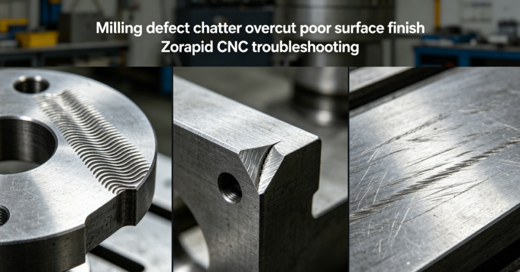
Defect 1: Chatter (Vibration Wave Marks)
What you see
Evenly spaced ripples, wavy vertical lines on sidewalls, loud humming or rattling noise during cutting.
Tool edges chip quickly, and surface texture turns jagged no matter how you adjust feedrate.
Core Root Causes (System Resonance)
Chatter is regenerative vibration. The tool deflects on one pass, then cuts into the ripple it left on the previous rotation. The vibration amplifies until the whole cut becomes unstable.
We split the triggers into four categories:
- Insufficient rigidity (#1 cause) Tool overhang longer than 3× tool diameter creates massive deflection. Long slender end mills vibrate even with moderate cutting load. Loose vises, thin-walled workpieces and worn spindle bearings make vibration far worse.
- Wrong tool geometry Equal-flute end mills build harmonic vibration. Too many flutes engaged in the cut spike radial cutting force and trigger resonance immediately.
- Bad speed-feed balance Chip load becomes too light. The tool rubs instead of shearing material, kicking off continuous chatter. Simply lowering RPM often makes the vibration worse.
- Abrupt changes in tool engagement Sharp corners, sudden stepovers, and heavy radial cuts spike cutting force and shake the tool off its stable path.
Zorapid Proven Fixes
- Stick strictly to the golden rule: Keep tool stick-out under 3× tool diameter. Use stub-length carbide cutters wherever possible to cut deflection by more than half.
- Switch to variable helix / unequal pitch end mills. These break harmonic resonance and eliminate regular wave marks on steel and titanium jobs.
- Adjust parameters to maintain proper chip load: If chatter starts, raise feed before lowering spindle RPM. Never let the tool just rub the workpiece surface.
- Rewrite toolpaths with trochoidal milling to keep consistent low tool engagement through corners, no sudden force spikes.
- Use hydraulic shrink-fit holders instead of standard ER collets to reduce tool runout below 0.002mm.
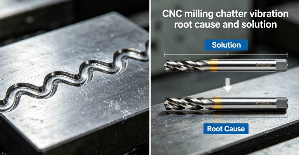
Defect 2: Overcut (Gouging, Corners Cut Too Deep)
What you see
Internal corners and pocket walls end up smaller than nominal size. Programmed radius stays clean, but actual machined corners get gouged and oversize on the inside.
CMM reports show negative dimensional deviation even with correct cutter compensation settings.
Core Root Causes
- Tool deflection under radial cutting load Side milling pushes the cutter sideways. The tool bends outward while cutting the wall. When exiting the corner, spring-back pushes the edge into the material, creating overcut gouges. This is the top reason pocket corners always oversize.
- Incorrect cutter radius compensation CAM software compensation does not account for tool bending. If you turn on radius comp during sharp corner transitions, the controller overshoots the toolpath.
- CNC corner deceleration overshoot The machine slows down abruptly when rounding corners. Servo lag makes the tool travel past the programmed line, leaving a gouge on the inner radius.
- Climb milling vs conventional milling mix-up Conventional milling pulls the tool into the workpiece, dramatically increasing deflection and overcut on deep pocket walls.
Zorapid Proven Fixes
- Split roughing and finishing strictly. Leave a 0.08~0.12mm stock on all walls for a light finishing pass to reduce side load and bending.
- Turn cutter compensation OFF for corner entry moves. Only activate comp after the tool reaches the straight wall section.
- Tune machine servo parameters to reduce corner overshoot, or add small arc lead-in/lead-out moves so the tool never stops abruptly at corners.
- Standardize climb milling for all finishing cuts. This pushes the cutter away from the part instead of pulling it into the material, cutting deflection and overcut by 70%.
- For deep pockets, use shorter, larger-diameter tools to improve rigidity and eliminate spring-back gouging.
Defect 3: Poor, Streaky Surface Finish (No Chatter, Still Rough Texture)
What you see
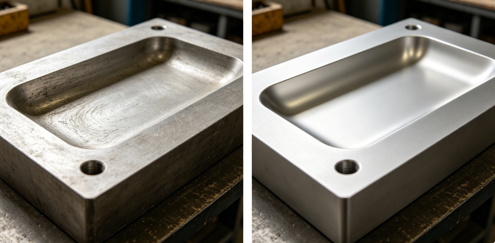
No obvious wave marks from vibration, but the surface has fine feed lines, streaks, burn marks or uneven polishing texture. Ra value jumps from Ra 0.4μm up to Ra 1.6μm even with sharp new tools.
Core Root Causes
- Feed line pattern not matched to finishing stepover Large stepover leaves visible scallops between cutting passes. Many programmers only adjust spindle speed and ignore the radial stepover, which directly sets theoretical surface roughness.
- Built-up edge (BUE) on the cutting edge Aluminum and soft steel material welds onto the tool tip. This built-up edge drags across the part surface, scratching long streaks and creating uneven texture.
- Insufficient coolant & thermal rubbing Dry cutting causes edge heating. The tool rubs instead of shearing material, smearing the surface and leaving dull, streaky finish, especially on POM, aluminum and mold steel.
- Tool runout from low-quality collets Minor shank wobble creates uneven cutting edges. One flute cuts deeper than the rest, leaving inconsistent feed lines across the entire machined face.
- Mixed finishing strategies Switching between linear raster and contour finishing leaves mismatched toolpath lines that show up clearly on polished mold surfaces.
Zorapid Proven Fixes
- Match stepover strictly to tool nose radius. For a 0.8mm radius ball end mill, set stepover below 0.12mm to keep theoretical scallop height tiny.
- Use high-pressure MQL flood coolant for aluminum. Add anti-BUE coating on carbide cutters to stop material from sticking to cutting edges.
- Keep total tool runout below 0.003mm with balanced shrink holders. Replace worn collets before running finishing programs.
- Lock all finishing toolpaths to one consistent raster direction. Avoid mixing contour and parallel passes on cosmetic surfaces.
- Add a final light spring cut with zero stock removal to wipe away feed lines without heavy cutting load.
Cross-Defect Link: How One Problem Triggers the Other
We see this chain reaction every day in our workshop:
- Long tool → tool deflection → overcut corners
- Heavy side load from deflection → unstable cutting → chatter vibration
- Chatter + built-up edge → rough streaky surface finish
If you only fix surface texture without improving rigidity, you will keep bouncing between all three defects.
Our troubleshooting sequence is always rigid setup first, then tool selection, then CAM path optimization, and adjust cutting parameters last.
Real Zorapid Case Study: Mold Steel S136 Pocket Milling
Project Condition
Hardened S136 mold pocket, finishing requirement Ra ≤ 0.4μm, ±0.008mm corner tolerance.
Original Defects
- Heavy chatter waves on vertical walls
- Inner corners overcut by 0.015mm
- Visible feed line streaks, surface Ra hit 1.8μm
Root Cause Audit
- Tool overhang reached 6× diameter (massive deflection)
- Conventional milling caused tool pull-in and gouging
- Stepover too large, no high-pressure coolant
- Equal-flute end mill triggered harmonic vibration
Optimized Process
- Switched to short stub tool, overhang reduced to 2.5× diameter
- Changed all finishing passes to climb milling + arc lead-in moves to eliminate corner overcut
- Upgraded to variable helix anti-chatter end mill
- Narrowed finishing stepover + turned on high-pressure flood coolant to stop BUE
Final Result
Zero chatter, zero corner gouging, surface Ra stabilized at 0.32μm, all corners held within tolerance on the first run.
Quick Troubleshooting Checklist
Chatter wave marks:
- Shorten tool overhang
- Switch to variable-flute cutters
- Reduce radial stepover to lower cutting force
- Tune spindle speed to escape resonance range
If you see corner overcut & gouging:
- Use climb milling exclusively for finishing
- Add lead-in arcs before sharp corners
- Leave thin stock for a light final pass
- Avoid activating radius compensation at corner points
If you see streaky poor surface finish with no chatter:
- Tighten finishing stepover to reduce scallop height
- Boost coolant pressure to eliminate built-up edge
- Control tool runout with high-grade holders
- Keep one consistent finishing toolpath direction
Why Zorapid Minimizes Milling Defects On All Jobs
- We run pre-job rigidity checks on tool stick-out, workholding and spindle runout before every finishing program
- Our CAM team uses anti-chatter trochoidal toolpaths and climb milling as standard practice for high-finish parts
- VERICUT simulation catches corner overshoot and compensation errors before the code hits the machine
- We separate roughing and finishing stock strictly to limit tool deflection and spring-back gouging
- We maintain strict tool holder balance and coolant pressure to avoid BUE and feed-line surface defects
- First-pass yield for Ra 0.2μm precision finishing stays above 97% across aluminum, titanium and hardened mold steel
Conclusion
Chatter, overcut and poor surface finish are not random bad luck.
They form a predictable chain reaction starting from weak rigidity, poor tool selection, flawed CAM toolpaths and unstable cutting conditions.
Tweaking RPM and feed alone will never permanently fix these milling defects. You have to fix the root mechanical and programming issues first.
At Zorapid, we build rigidity and stable cutting into every program from the DFM stage, so your parts hit dimensional tolerance and surface finish specs on the first cut with minimal rework.
Send your pocket or side milling CAD files, and our team will run a free process review to eliminate chatter, overcut and surface roughness issues upfront.
FAQ
Why do corners keep overcutting even with correct cutter compensation?
Tool deflection bends the cutter outward during side milling. When exiting the corner, the tool springs back inward and gouges the material. Adding lead-in arcs and light finishing stock stops this spring-back overcut.
Can I eliminate chatter just by slowing down spindle speed?
Usually no. Reducing RPM often pushes the cut right into harmonic resonance. The better fix is shortening the tool and lowering radial tool engagement before adjusting speed and feed.
What causes streaky surface finish without chatter waves?
Built-up edge on the tool tip, excessive stepover creating scallops, or high tool runout from worn collets. Flood coolant and tighter stepover will clear up most streaking issues quickly.
Does climb milling reduce overcut better than conventional milling?
Yes. Conventional milling pulls the cutter deeper into the workpiece and increases deflection. Climb milling pushes the tool away from the part, drastically cutting corner gouging and dimensional deviation.
How much tool overhang will trigger chatter?
Once stick-out exceeds 3× tool diameter, rigidity drops sharply and vibration risk jumps exponentially. For finishing work, we cap overhang below 3× diameter as a strict workshop rule.


