
Author: Zorapid.Ltd
Getting clean ejection sounds simple until you pull a part out and see drag marks, white cracks, or stuck plastic stuck tight in your mold cavity.
We run 3,000㎡ precision molding & tooling workshops at Zorapid. We fix hundreds of demolding failures every month. 80% of these costly scrap issues boil down to one tiny detail: poorly designed draft angles.
You can nail wall thickness, gate position, and cooling lines perfectly. Still, insufficient draft will ruin cosmetic surfaces, crack thin walls, and wear down your expensive mold steel.
This practical guide breaks down draft angle rules you can plug directly into your CAD files. We cover material limits, textured surface rules, deep cavity tweaks, and real production fixes to eliminate demold damage once and for all.
If you are designing NPI prototypes or high-volume tooling, these DFM rules will cut your scrap rate and shorten your molding cycle time.
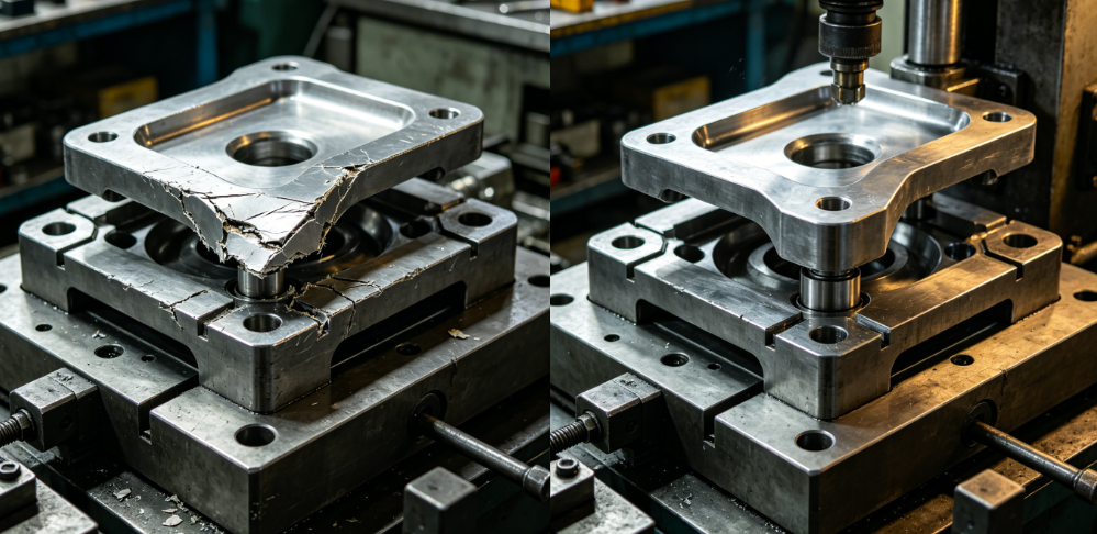
What Exactly Is a Draft Angle?
Every vertical wall parallel to your mold opening needs a slight taper. That taper is your draft angle.
Molten plastic shrinks tightly against core steel after cooling. Without this small taper, the plastic grabs the mold surface hard. When the ejector plate pushes the part out, friction tears the plastic surface.
- Zero draft = forced ejection = scratches, whitening, deformation
- Proper draft = parts slide free with minimal friction
- Draft always follows the mold opening direction along the parting line
What Demold Damage Does Bad Draft Cause?
We list the most frequent defects we see at Zorapid’s molding shop, all triggered by missing or insufficient draft:
- Surface drag lines & scuff marks The plastic scrapes across polished cavity steel during ejection. Cosmetic housings become unusable right out of the first shot.
- Whitening & micro-cracks on rigid plastics (PC, GF-PA66) Excessive pulling stress creates tiny fractures on part walls. This kills structural performance for medical and automotive components.
- Thin-wall bending & warpage Vacuum suction locks the part onto the core. Uneven ejection bends delicate thin-walled structures permanently.
- Mold cavity wear & grain peeling Forced ejection grinds plastic against textured mold surfaces. Your expensive etched grain wears out after a few thousand cycles.
- Ejector pin punch-through Operators crank up ejection pressure to free stuck parts. Pins punch holes right through your plastic walls.
No amount of mold temperature tuning or injection pressure adjustment will fix these problems. You must add correct draft in your 3D model before cutting steel.
Match Draft Angle to Surface Finish
This is the rule every toolmaker follows. More texture always needs more draft angle.
Polished steel slides easy. Etched grain catches plastic during release.
| Mold Surface Finish | Minimum Draft Angle | Main Risk If Draft Is Too Low |
|---|---|---|
| SPI A High Polish | 1.0° ~ 2.0° | Fine scratch lines on glossy surfaces |
| Matte / Light Grain Texture | 2.0° ~ 3.0° | Surface hazing & scuffing |
| Deep Heavy Texture / Grain | 3.0° ~ 7.0° | Plastic tears, grain pulls material off parts |
| Deep Core Tall Walls (>50mm) | Add +0.5° for every extra 50mm depth | Vacuum lock + stuck deep features |
Quick factory tip from our senior mold engineers:
For every 0.025mm depth of mold texture, add 0.5° extra draft. This stops plastic from catching inside grain pockets during ejection.
Draft Angles Tuned By Plastic Material
Different resins shrink and grip mold steel differently. Soft flexible plastics release easily. Glass-filled rigid plastics clamp tight against cores.
Below is our shop’s standard minimum draft data for common engineering plastics (tested across 2,000+ Zorapid molding projects):
- Soft low-shrink materials (PP, TPE, TPU): 0.25° ~ 0.5° minimum draft These flexible polymers stretch slightly. Even small draft works well for small disposable parts.
- General-purpose plastic (ABS, POM, HDPE): 0.5° ~ 1.5° standard draft Balanced shrinkage. 1° per side works for most consumer product housings.
- Rigid engineering resin (PC, PC+ABS, PEEK): 1.0° ~ 2.0° minimum draft Stiff plastic cannot stretch during ejection. Low draft creates immediate stress cracks.
- Glass-filled grades (GF-PA66, GF-ABS, GF-PC): 1.5° ~ 3.0° draft minimum Glass fibers scratch mold steel and boost friction. Always bump draft up for filled materials.
We often run MOLDFLOW demolding simulation before tooling steel cuts. The simulation predicts core clamping force and adjusts draft automatically for high-shrink resins.
Draft Design For Ribs, Bosses & Deep Cavities
Flat outer walls are easy. Small internal ribs and deep blind cores are where most engineers cut corners.
Rib Draft Rules
- Thin ribs (wall <1.2mm): Apply 0.5° minimum draft on both sides
- Tall ribs (height >25mm): Increase draft to 1.0° per face If you leave ribs zero draft, the thin plastic will crack the second the ejector pushes the part free.
Deep Blind Cores
Tall cylindrical cores create a strong vacuum seal. The part sticks hard even with basic 1° draft.
Our fix at Zorapid:
- Boost draft from 1.5° up to 3° on deep core surfaces
- Add small air vents to break vacuum pressure
- Use two-stage ejection instead of single push-off
This eliminates stuck deep-cavity parts without ruining dimensional tolerance.
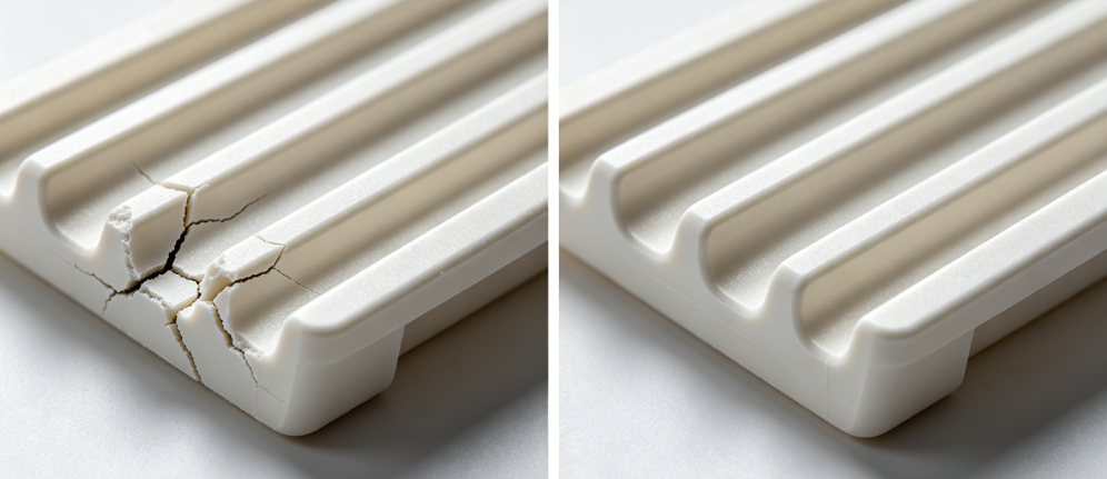
Most Common Draft Angle Mistakes We Fix Every Week
We review hundreds of customer STEP files for DFM analysis before starting mold builds. These four mistakes cause 90% of demold damage:
- Only adding draft to outer surfaces, ignoring internal cores & ribs External walls release fine, but internal stuck ribs crack the whole component. Always apply draft on both cavity and core sides.
- Using the same draft angle for polished and textured surfaces Engineers apply 1° draft on deeply grained molds. Plastic catches inside texture and tears during ejection.
- Cutting draft too small to hold tight dimensional tolerance Designers shrink draft down to 0.25° just to hold size. The tradeoff is stuck parts and endless scrap. We balance draft and tolerance via core offset instead of cutting taper too low.
- Forgetting draft on undercut adjacent vertical walls Lifter and side-slide mechanisms leave nearby vertical surfaces with zero taper. These small vertical strips scratch severely during mold opening.
Our DFM team flags all missing draft features within 24 hours once we receive your 3D files. We revise the model without shifting your critical assembly dimensions.
Zorapid’s Practical Fixes When You Cannot Increase Draft
Sometimes product appearance or tight GD&T tolerances block you from adding larger draft angles. We use these shop-proven solutions to avoid ejection damage without expanding taper:
- Super-polish core steel to SPI A finish Smoother mold surfaces cut friction drastically, lowering ejection pulling force.
- Add PTFE mold coating on high-friction core areas The low-friction coating lets rigid engineering plastics slide free with minimal draft.
- Switch to balanced multi-point ejection layout Even pressure distribution prevents localized stress that cracks thin walls.
- Break vacuum with air poppet valves on deep cores No vacuum lock = less clamping force between plastic and steel.
- Adjust cooling cycle to lower part shrinkage Slower, uniform cooling reduces how tightly the plastic grips the mold core.
We combine these tweaks for precision medical and semiconductor molded parts where draft is limited by strict size requirements.
Real Zorapid Case Study – Demold Damage Solved With Draft Optimization
Project Background
Automotive GF-PA66 connector housing, deep internal bosses + textured exterior grain.
Original design: 0.5° draft on all walls.
Production issue: 35% scrap rate from whitened cracks and grain peeling on outer surfaces.
Our Revision
- Bumped exterior textured wall draft from 0.5° up to 3.0° for grain release
- Set internal boss draft to 1.5° to stop core sticking
- Polished all core steel + added small venting on deep blind features
Result
Scrap rate dropped below 1.2%. Ejection cycle shortened by 6%. The textured surface released cleanly without tearing for 500,000+ molding shots.
We completed the DFM draft revision and issued updated STEP files before mold steel machining started. No costly rework on finished tooling.
Quick Draft Angle Checklist You Can Save For DFM Reviews
Run this list on every new part before mold release:
All vertical walls along mold opening have defined draft (internal + external)
Textured surfaces get extra draft matched to grain depth
Glass-filled rigid resins use higher taper than commodity plastics
Tall ribs & deep cores have increased draft + vacuum venting
Zero-draft vertical strips next to lifters are eliminated
Ribs have bilateral draft, not just one-sided taper
If you tick every box, you will almost never face ejection-related part damage.
Why Zorapid Gets Draft Design Right From The First Shot
With 20+ years of injection mold building and precision molding, our engineering team handles NPI tooling all the way to mass production for aerospace, medical, automotive and electronics clients across Europe and North America.
What we deliver:
- Free DFM analysis with full draft angle audit on your 3D files
- MOLDFLOW demolding simulation to calculate core clamping stress
- Balanced draft design that protects both cosmetic appearance and critical dimensional tolerances
- Mold surface & coating plans matched exactly to your draft values
- Zero post-machining rework caused by poor ejection design
We avoid the trial-and-error scrap that eats into your project budget and lead time.
Conclusion
Demold scratches, cracks and stuck parts rarely come from bad machine settings. They come from under-designed draft angles in your 3D CAD model.
Follow three core rules:
- Boost draft sharply for textured mold surfaces
- Adjust taper based on plastic material shrinkage and filler content
- Never skip draft on internal ribs, bosses and deep blind cores
Small taper adjustments in your part design save thousands in scrap, mold repair and production downtime.
Send your STEP or IGES files to Zorapid today. Our engineers will run a full draft audit and send revised DFM data within one working day.
FAQ
Can I run zero draft on polished precision parts?
Zero draft carries huge ejection risk even on glossy steel. We recommend a minimum 0.25° taper unless you implement air ejection and super-finished cores. Zero draft always leads to forced ejection damage in high-volume runs.
How much extra draft do I need for deep tall cavities over 100mm?
Add 0.5° draft for every additional 50mm of core depth, plus vacuum break vents to eliminate suction lock.
Will extra draft mess up my part dimensional tolerance?
We offset core and cavity dimensions to compensate for taper. Your critical mating sizes stay within GD&T specs while keeping ejection smooth.
Does draft direction matter on the parting line?
Always draft cavity walls outward and core walls inward, strictly following mold opening movement. Reversed draft creates immediate undercuts and part jams.


