Publisher: Zorapid.Ltd
Long thin shafts with high length-to-diameter (L/D) ratios are the most frustrating turning job on any CNC lathe.
The workpiece acts like a weak spring. Once cutting starts, violent vibration kicks in.
You get wavy fish-scale chatter marks all over the surface. The middle of the shaft bows downward under cutting pressure. OD dimensions drift from end to end.
Even if you nail the size while clamped, the shaft springs out of straightness after you release the tailstock.
For aerospace actuator pins, medical threaded rods and automation precision shafts, vibration ruins surface quality and tight straightness tolerance.
At Zorapid, we turn hundreds of high L/D slender shafts (L/D up to 35:1) from titanium, alloy steel and stainless steel for EU and North American OEMs.
We lock out chatter and keep shaft straightness below 0.008mm by strictly controlling rigidity, cutting force, fixturing and programming.
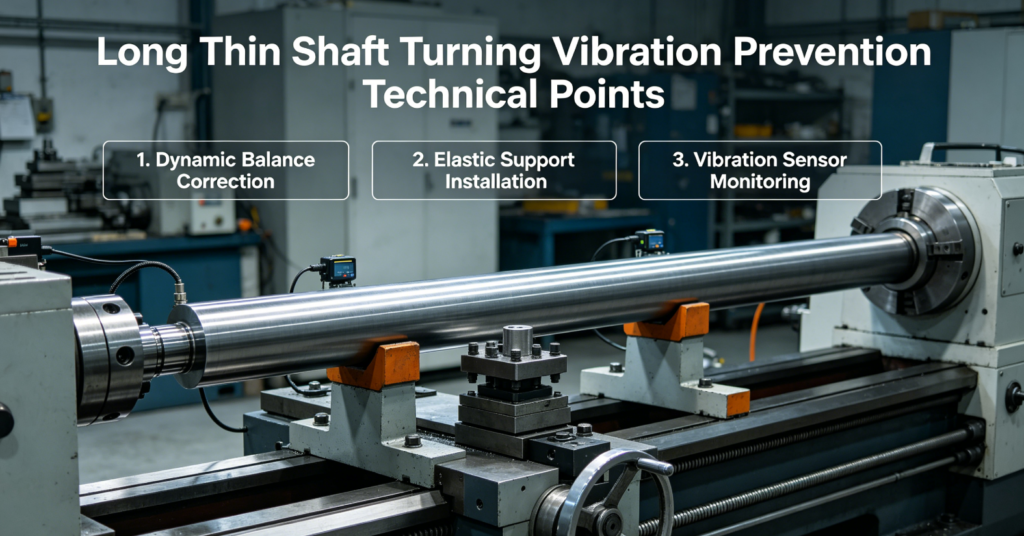
Core Root Cause of Slender Shaft Vibration
All chatter and bending comes down to three physical problems:
- Low workpiece rigidity. Long thin bars bend easily under radial cutting force. Resonance builds quickly.
- Excessive radial tool pressure pushes the shaft sideways during each cut.
- Thermal expansion creates axial compression, buckling the bar even without heavy cutting loads.
Most shops only tweak spindle RPM, but real stability requires upgrading workholding, tool geometry, cutting path and parameters together.
First follow this basic L/D shop rule:
- L/D ≤ 5: Simple chuck + tailstock setup works fine
- L/D = 5 ~ 15: Must use live tailstock center
- L/D > 15: Mandatory to add steady rest or follow rest support
- L/D > 25: Use tension pulling clamping + segmented turning to avoid mid-span bending
Optimize Workholding to Boost Workpiece Rigidity
Bad clamping creates 60% of all slender shaft bending and vibration. We strictly follow these four rules.
Use Floating Elastic Live Center, Never Rigid Dead Center
When the shaft heats up during turning, it stretches lengthwise.
A locked rigid dead center creates heavy axial compression. The slender bar buckles upward instantly.
Fix:
Install a spring-loaded floating live center on the tailstock. It absorbs thermal elongation without building compressive stress.
Keep tailstock pressure light. Too much pre-load still bends thin bars.
Reduce Chuck Clamping Stress
Over-tight three-jaw chucks squeeze the shaft out of round right at the grip end.
Improvement:
Use a short clamping length, add a thin copper soft liner inside jaws. Never clamp more than 8~12mm of the bar end.
For ultra-slender stock, switch to four-jaw independent chuck for even, low-distortion gripping.
Add Steady Rest & Follow Rest to Cut Unsupported Length
Shaft rigidity rises sharply when you split the long span into short sections.
- Steady rest (fixed): Mount at the midpoint of the shaft to stop mid-span bending
- Follow rest (moving): Bolt onto the lathe carriage, traveling right behind the cutting tool. It supports the workpiece instantly as the tool moves along the bar.
When using roller rests:
Use brass or POM rollers instead of steel rollers to avoid scoring the finished surface. Keep roller pressure just enough to touch the bar, do not squeeze hard.
High L/D Shaft: Apply Axial Tension Clamping
For shafts longer than 25× diameter, we add a pull fixture on the tailstock side.
We keep the entire bar under mild tension during turning. Tension eliminates bending tendency and suppresses vibration drastically.
Tool Geometry — Cut Radial Cutting Force to Minimum
Radial (side) cutting force is the main trigger for shaft deflection. We redesign turning tools specifically for slender shafts.
Choose 90° Lead Angle Tool (Non-Negotiable Rule)
- Main cutting angle Kr = 90° This design almost cancels radial thrust force. The tool only pushes forward along the shaft instead of pressing sideways to bend the bar. Do not use 75° or 60° general-purpose turning inserts — they generate too much side pressure and start vibration immediately.
Keep Insert Nose Radius Tiny
Large nose radii dig into the workpiece and create heavy radial load.
Finishing insert nose radius: R0.1 ~ R0.2 only.
Small radius produces thin chips and reduces tool push-back on the slender bar.
Keep Tool Overhang Ultra Short
Shorten the tool holder projection as much as possible. Even 5mm extra overhang makes the tool holder vibrate and amplify workpiece chatter.
Set tool tip exactly on the spindle centerline, or 0.1~0.2mm above center. Tools below center will dig into the shaft and trigger resonance.
Use Sharp Positive-Rake Inserts
High positive rake makes cutting shearing light, reduces cutting resistance and lowers heat generation. Dull inserts increase friction and start wave marks on the OD surface.
Optimize Cutting Path & Turning Sequence
Long continuous full-length turning lets vibration build up over the whole shaft. We use segmented short-cut programming to break resonance.
Segmented Short-Section Turning (Best Anti-Chatter Program Trick)
Instead of one long pass from chuck to tailstock:
Split the shaft into 25~40mm short segments.
Finish one short section fully, then jump to the next segment. Do not run a continuous long tool path.
This breaks the wave pattern left by the previous cut, so regenerative chatter cannot form.
Machine from Tailstock toward the Chuck
Cut direction matters a lot.
Tool moving toward the chuck keeps the shaft under mild tension from cutting force, instead of compressing and bending the bar upward.
We strictly program the feed direction from tailstock end back toward the headstock for all long shaft roughing and finishing.
Rough First, Release Stress Before Finishing
Rough turning locks heavy cutting stress inside the bar.
Process flow:
- Rough turn all OD, leave 0.25~0.35mm uniform finishing stock
- Loosen tailstock pressure fully, let the shaft cool naturally and release residual stress
- Re-adjust live center tension lightly, then run finishing passes
Skipping this relaxation step leads to post-machining bowing after unclamping.
Tuned Feeds, Speeds & Spindle Anti-Chatter Control
Resonance happens when spindle RPM matches the shaft’s natural vibration frequency. Constant RPM creates stable wave patterns.
Avoid Fixed Constant RPM — Use Spindle Speed Variation (SSV)
Turn on spindle fluctuation function on your CNC system.
Let RPM swing 8~12% up and down continuously during cutting.
This breaks regenerative chatter so vibration waves cannot repeat and amplify.
This single parameter change eliminates 70% of fish-scale surface ripples without modifying tooling.
Keep Light Chip Load, Shallow Finishing Passes
- Roughing depth of cut: ≤ 0.3mm per pass
- Finishing depth of cut: 0.08 ~ 0.15mm light cuts only Heavy deep cuts overload the thin shaft and trigger bending. Keep feed rate steady; avoid extremely slow feed which causes tool rubbing and heat buildup.
Control Cutting Heat
Excess heat causes uneven thermal expansion and shaft bowing.
Use high-pressure through-tool coolant or MQL minimum quantity lubrication.
Pause the program periodically to let the bar cool down between long cutting segments.
Do not let the shaft turn red hot in the middle section.
Pre-Material Stress Treatment to Prevent Post-Machining Bending
Many long shafts look straight on the lathe but bend right after unclamping.
This is caused by residual stress inside cold-drawn bar stock.
Material Prep Rules
- Use stress-relieved annealed bar stock for high L/D slender shafts. Cold-drawn raw material always contains high surface tension.
- If you must use cold-finished bar, run low-temperature stress relief before turning. Heat the bar to 550°C and slow cool to release locked stress.
- Machine the OD symmetrically; avoid removing material only from one side of the bar. Uneven stock removal releases stress unevenly and creates permanent bending.
5 Common Vibration Defects & Fast Shop Floor Fixes
| Defect | Root Cause | Instant Correction |
|---|---|---|
| Fish-scale chatter waves on OD | Radial force + fixed RPM resonance | Switch to 90° low-radial tool + activate SSV variable spindle speed |
| Middle of shaft bows downward | Unsupported long span | Install follow rest moving behind the cutting tool |
| Shaft buckles upward after heating | Locked dead center thermal compression | Replace with floating elastic live center, reduce tailstock preload |
| Dimension drifts from chuck end to tailstock | Continuous long cutting path | Split into segmented short-section turning |
| Shaft springs bent after unclamping | Bar residual stress | Use annealed stress-relieved bar + roughing stress relaxation pause |
Zorapid Full Anti-Vibration SOP for Long Thin Shafts
Copy this workflow to hold straightness ≤ 0.008mm for high L/D slender parts:
- Use pre-annealed stress-relieved bar stock
- Short soft-jaw clamping + floating spring live center with light tailstock pressure
- Install steady rest at mid-span + follow rest moving with the cutting tool
- Mount 90° main-angle insert with tiny R0.1~R0.2 nose radius, tool tip on center height
- Rough turn with shallow cuts, then pause for stress relaxation and full cooling
- Program segmented short-section turning, cutting from tailstock back toward the chuck
- Turn on spindle speed variation (SSV) to break regenerative chatter
- Run light finishing passes with through-tool coolant
- Keep the part clamped until fully cooled before final dimensional inspection
Measurable Production Result:
- Old process: Chatter + bending, straightness error up to 0.035mm
- Optimized anti-vibration process: Zero wave marks, total shaft bow controlled below 0.007mm
Real EU Client Case Study
A German aerospace client sent us 316 stainless steel slender shafts with L/D = 28:1.
Their original process had two major issues:
- Severe fish-scale chatter covering the whole OD surface
- Mid-span bending reaching 0.032mm, failing straightness requirements
We revised the whole process strictly following our anti-vibration technical points:
- Switched rigid dead center to floating live center to eliminate thermal buckling
- Replaced standard inserts with 90° low-radial-force tool with R0.15 nose radius
- Added a traveling follow rest right behind the cutting tool
- Activated spindle speed variation and changed the program to segmented short-section turning
- Added a cooling pause after roughing to release cutting stress
Final outcome:
No vibration wave marks left on the shaft surface. Full-length straightness held within 0.006mm, and all OD dimensions stayed consistent from end to end. The parts passed aerospace geometric inspection without rework.
Conclusion
Vibration and bending on long thin shafts are not unavoidable.
Stable turning relies on five linked technical points:
- Upgrade workholding with floating live centers and moving follow rests to raise rigidity
- Use 90° low-radial-geometry tools to eliminate side thrust force
- Split long cuts into segmented short sections to break chatter wave patterns
- Activate variable spindle speed to stop regenerative resonance
- Relieve material stress both before and during machining to prevent post-cut bending
You do not need expensive damping toolholders to fix most slender shaft problems. Reorganize your fixturing, tooling and CNC program first, and most vibration will disappear immediately.
At Zorapid, we specialize in high-precision long thin shaft turning for aerospace actuators, medical threaded pins and automation slender rods. We control chatter and straightness consistently for high L/D parts across stainless steel, titanium and alloy steel grades for European and North American OEMs.
If you keep fighting shaft vibration, bending and surface chatter, send your print and L/D ratio. Our lathe process engineers will deliver a full anti-chatter setup and parameter plan for your next batch.
FAQ
Is follow rest better than steady rest for slender shaft turning?
Yes. A fixed steady rest only supports one fixed position. A follow rest travels right behind the cutting tool, supporting the workpiece exactly where cutting force is applied. It suppresses mid-span bending far better for long shafts. We combine both for L/D higher than 20:1.
Can SSV spindle variation fully eliminate regenerative chatter?
It breaks the repeated wave pattern left on the workpiece surface. When the spindle speed keeps fluctuating, the next cut never lines up with the previous ripple. This is the most cost-effective anti-chatter adjustment without buying new tooling.
Why does the shaft bend only after I release the tailstock?
Trapped residual stress from rough turning or cold-drawn bar stock. The clamps hold the bar straight during cutting. Once released, stress releases and the bar springs into a curved shape. Adding a cooling pause after roughing solves most of this issue.
Is higher spindle RPM always better to avoid vibration?
No. Too high RPM hits the natural frequency of the slender shaft and triggers violent resonance. We pick a stable mid-range RPM then turn on speed fluctuation instead of chasing higher spindle speed blindly.