Publisher: Zorapid.Ltd
Tiny precision die components — micro punches, narrow die slots, small carbide inserts and stamping die openings — push Wire EDM to its absolute limit.
You program the path carefully, lock in offset values, and run the cut.
Then you get three frustrating results:
The wire lags behind the programmed path, throwing profile dimensions off.
Sharp inner corners collapse or round over unexpectedly.
Thin small die blanks shift size from heat stress, so parts drift out of tolerance mid-batch.
Single-pass rough cuts leave a hard recast layer, which distorts dimensions long after machining finishes.
For high-speed progressive stamping tools, even 0.003mm deviation causes pin breakage and premature die wear.
At Zorapid, we run Wire EDM for hundreds of tiny hardened die components (DC53, D2, tungsten carbide) for European and North American stamping OEMs every month.
We consistently hold tolerance stable within ±0.0015~±0.002mm across full batches.
Today we break down every critical tolerance control point specifically for small micro die parts, with zero guesswork. All methods are tested daily on our Sodick wire EDM cells.
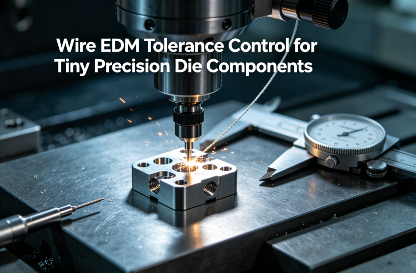
The Unique Tolerance Risks of Tiny Die Parts
Small thin die blanks create problems you never see on large thick blocks:
- Short closed profiles make the wire slow down sharply at corners. Wire lag becomes exaggerated on small slots and sharp corners.
- Small workpieces heat up fast from spark energy. No mass to absorb heat, so thermal expansion shifts dimensions quickly.
- Narrow internal gaps limit flushing. Debris gets trapped inside small die openings, causing unstable spark gaps and random dimensional variation.
- Thin die inserts bend slightly under clamping force, creating part-to-part inconsistency across batches.
- A single rough cut leaves a brittle recast layer. This thin surface layer relaxes and distorts the micro profile after wire cutting completes.
Most operators only adjust wire offset values. Real stable tolerance requires controlling wire behavior, cutting sequence, flushing, thermal drift and clamping all together.
Control Wire Straightness & Tension to Eliminate Lag Error
Wire lag is the No.1 cause of out-of-tolerance profiles on small closed die cavities.
The brass wire bends slightly under spark pressure, falling behind the programmed path. This error multiplies on tiny short slots.
Zorapid Standard Wire Setup for Micro Die Work
- Use ultra-fine high-tensile brass wire: 0.10mm ~ 0.15mm diameter for micro slots smaller than 0.3mm width.
- Crank up wire tension to the upper stable limit: 22~26N for 0.15mm brass wire. Tight tension keeps the wire perfectly straight and minimizes bending lag on short profiles.
- Slow down feed rate sharply when entering small closed pockets. Never run high feed on short die openings.
- Turn on automatic wire lag compensation built into the EDM control. Manually tweak the offset value after the first test cut on a trial blank.
Critical rule for small corners:
Reduce servo speed as the wire approaches sharp corners. Slow movement prevents wire deflection and stops inner corners from rounding over.
Strict Multi-Pass Cutting Sequence — Remove Recast Layer & Thermal Stress
One-shot rough cutting will never hold tight tolerance on hardened tiny die steel.
High-energy sparks melt the surface and leave a hard recast layer. This thin layer creates locked stress, and the micro die profile shifts size after machining.
Three-Stage Cutting SOP For Micro Die Inserts
- Rough cut: High spark energy, leave 0.025~0.03mm stock all around the profile. Remove bulk material fast.
- First skim pass: Lower spark power, trim most remaining stock and erase most heat-affected zones.
- Final finish skim: Ultra-low pulse energy, tiny spark gap, minimal material removal (only 0.005~0.008mm stock cut). This pass locks final dimension without introducing new thermal stress.
Never skip the finish skim pass for die components requiring ±0.002mm tolerance.
Single-cut parts always drift after cooling. Multi-pass cutting eliminates recast layer and stabilizes dimensions permanently.
Measurable result:
Single rough cut: tolerance drifts ±0.012mm
3-pass rough + double skim: stable tolerance locked within ±0.002mm
Optimize Start Hole & Entry Path to Avoid Notch & Profile Distortion
Bad start hole placement ruins small die openings right at the wire entry point.
If you drill the start hole directly on the cutting path, you leave a visible notch that breaks the continuous profile accuracy.
Entry Programming Rules For Tiny Closed Die Profiles
- Drill the start hole 0.3~0.5mm off the actual cutting path, not directly on the contour.
- Use an arc lead-in path instead of a straight linear entry. The wire eases gradually into the cut, so spark energy does not create a local indentation.
- Shift the entry position on each skim pass. Never start every cut at the same spot. This spreads spark erosion evenly and prevents localized dimensional shift.
- Keep start holes clean and burr-free. Any drilling slag creates unstable sparking right at the wire entry.
For small narrow die slots: always drill two small start holes for better upper/lower flushing.
Perfect Flushing To Stabilize Spark Gap Inside Tiny Die Cavities
Small enclosed die openings trap eroded steel sludge.
Debris floating in the spark gap causes random short circuits, unstable discharge and inconsistent overcut.
This creates part-to-part variation even with identical offset settings.
Flushing Control For Micro Die Features
- Raise upper and lower jet pressure evenly. Keep water flow fully aimed directly at the cutting gap.
- Split long small slots into segmented cutting sections. Pause the program periodically to let fluid flush out trapped debris.
- Keep deionized water clean with stable conductivity. Dirty water changes spark gap conditions and creates unpredictable overcut values.
- On thin small die blanks, use full through-flushing instead of only side jet flushing.
Poor flushing accounts for nearly 40% of random tolerance scatter on micro die batches.
Clamping & Fixturing — Prevent Thin Die Blanks From Bending
Tiny thin die inserts flex easily under vise pressure.
Over-clamping squeezes the blank, and the profile springs back into shape after you release the part. Dimensions shift instantly.
Low-Distortion Fixturing Rules
- Use soft aluminum vise jaws with light clamping torque only. Never squeeze hardened small die blanks tightly.
- Support the entire bottom face of the part on a solid base plate. No overhanging thin sections during cutting.
- Locate on two stable datum holes instead of edge finding. Edge location introduces tiny repeatability error on small workpieces.
- After rough cutting, loosen the clamp slightly and let the part relax for 15~20 minutes before running finishing skim passes. Release clamping stress before final dimension locking.
Thermal Environment & Machine Compensation
Tiny die parts have very low thermal mass. Even 1°C temperature swing makes hardened steel expand or contract enough to break micron tolerance.
Strict Thermal Control Standard
- Keep the Wire EDM workshop held at 20±1°C constant temperature, no draft or air conditioning fluctuation.
- Warm up the machine for 30 minutes before running precision micro die batches. Let ball screws and wire guides reach stable operating temperature.
- Turn on the machine’s built-in thermal compensation function. The CNC automatically adjusts coordinate offsets as machine temperature rises.
- Let each small die part cool fully to ambient temperature before CMM inspection. Measuring hot parts will give false oversized readings.
For carbide micro die inserts, we also let blanks sit in the temperature-controlled workshop for 24 hours before clamping to stabilize material temperature fully.
Corner Parameter Tuning — Eliminate Rounding On Sharp Die Corners
Sharp inner die corners are the most difficult feature for Wire EDM.
When the wire hits a 90° corner, the machine slows feed, spark energy builds up, and the wire erodes extra material, rounding the sharp edge.
This ruins sharp die openings for precision stamping.
Corner Accuracy Programming Tweaks
- Enable corner dwell suppression. Reduce extra spark on-time when the wire reaches sharp corners.
- Program small corner lead-out arcs to slow wire movement gradually without excessive spark erosion.
- Lower peak current strictly on corner segments only. Keep high energy on straight sections and low energy on sharp corners.
- Use smaller wire offset values for corner finishing passes to limit over-erosion.
With these settings, we consistently hold sharp R0.02~R0.03 micro corners without excessive rounding.
6 Common Tolerance Defects On Tiny Die Parts & Fast Fixes
| Defect | Root Cause | Instant Correction |
|---|---|---|
| Whole profile oversized or undersized | Wrong wire offset + unstable spark gap | Calibrate offset on test blank; stabilize DI water conductivity |
| Sharp inner corners turn rounded | Excess spark energy at corner dwell | Reduce pulse on-time on corner segments; add lead-in arcs |
| Wire lags, curved features shift out of position | Low wire tension + high feed on short paths | Tighten wire tension; slow feed on small closed pockets |
| Part dimensions shift after cutting | Recast layer thermal stress | Add 2 skim finishing passes to remove heat-affected layer |
| Batch parts have inconsistent size | Poor flushing with trapped sludge | Boost through-flushing; segment cuts for debris removal |
| Thin die insert springs out of shape after unclamping | Over-tight vise clamping | Light jaw pressure; relax fixture between rough and finish |
Zorapid Full Tolerance-Control SOP For Micro Die Components
Copy this process to hold ±0.002mm stable tolerance on small hardened punch & die sets:
- Pre-stabilize hardened DC53 / carbide blanks in constant-temperature workshop
- Drill off-path start holes with arc lead-in entry, no direct path drilling
- Light clamping on full support plate; avoid squeezing thin die blanks
- Set high wire tension with 0.10~0.15mm fine brass wire
- 3-stage cutting: rough cut → first skim → low-energy final finish
- Optimize corner spark parameters to prevent edge rounding
- Maintain balanced upper/lower through-flushing to eliminate trapped sludge
- Run machine thermal compensation with warm-up cycle
- Cool part fully before CMM dimensional inspection
Measurable Production Result:
Old single-cut process: 21% scrap from drift and corner error
Optimized multi-pass Wire EDM process: First-pass yield >97%, consistent tolerance ≤ ±0.002mm across full batches
Real EU Client Case Study
A Belgian automotive stamping OEM sent us tiny DC53 hardened die inserts with 0.25mm narrow slots and sharp 90° inner corners.
Their original Wire EDM process had two major tolerance issues:
- Wire lag made curved profiles deviate up to 0.008mm from the CAD path
- Sharp corners kept rounding over, failing stamping blanking edge requirements
We revised the full process following our tolerance control rules:
- Switched to high-tension 0.12mm fine wire with lag compensation
- Split the job into rough + two low-energy skim passes to remove recast layer
- Rewrote entry paths with off-set start holes and arc lead-ins
- Tuned corner pulse energy to stop over-erosion on sharp die openings
- Added fixture relaxation after rough cutting to release clamping stress
Final outcome:
All slot profiles stayed within ±0.0018mm tolerance. Corners remained crisp without rounding.
The die set ran 900,000 stamping cycles without edge chipping or dimensional shift.
Conclusion
Tight Wire EDM tolerance on tiny precision die components does not just depend on good machine hardware.
Stable micron accuracy comes from seven linked controls:
- High wire tension to eliminate lag deflection on short small profiles
- Multi-pass rough + skim cutting to erase recast thermal stress
- Off-path start holes and arc entry to avoid entry notches
- Balanced through-flushing to keep spark gap consistent inside narrow cavities
- Low-pressure clamping to stop thin die blanks from springing out of shape
- Constant-temperature environment with machine thermal compensation
- Tuned corner spark parameters to keep sharp die edges crisp
You can eliminate nearly all batch variation and dimensional drift by reorganizing your cutting sequence and EDM programming.
At Zorapid, we specialize in Wire EDM for tiny hardened punches, die slots and carbide inserts for progressive stamping tools across Europe and North America.
We hold stable micron-level tolerance and keep sharp die edges with minimal batch scrap.
If you keep fighting profile drift, corner rounding and inconsistent die dimensions, send your DXF profile and material grade. Our EDM process engineers will build a full offset, wire tension and multi-cut parameter plan for your next micro die batch.
FAQ
How many skim passes do I need to hit ±0.002mm tolerance on small die parts?
One rough cut plus two finish skim passes works reliably. The first skim removes most recast layer, and the second low-energy pass locks the final dimension without adding new heat stress. Single-pass cutting cannot hold long-term stability on hardened tool steel die inserts.
Why do small die parts keep changing size after cooling?
The rough spark melts the surface and creates a thin hard recast layer. This layer holds residual stress. After the part cools, the surface relaxes and shifts the profile. Extra skim passes machine away this damaged layer completely.
Is thinner wire always better for micro die slots?
0.10~0.15mm wire is ideal for slots below 0.3mm width. Ultra-thin wire below 0.10mm vibrates easily and breaks frequently, introducing new dimensional inconsistency. Balance wire diameter and tension carefully.
Can I skip temperature control on small one-off die prototypes?
Even small thin steel blanks expand quickly from machine heat. Without a constant 20°C environment, you will see 0.003~0.005mm random size variation from part to part. Thermal stability remains critical for precision die work.