
Publisher: Zorapid.Ltd
Nearly 75% of CNC production cost is locked the moment you save your final 3D CAD file.
You finish product simulation, lock the part function, and send drawings out for RFQ.
Then the quote lands far above your budget.
Long cycle times, repeated fixture setups, frequent tool breakage, strict full-part inspection, and unexpected scrap all push the price higher.
You start negotiating machine rates and raw material pricing, but you still cannot hit your cost target.
Price bargaining only delivers small savings. DFM design optimization reliably cuts total CNC cost by a solid 20% without weakening part performance or assembly fit.
At Zorapid, we run free pre-production DFM reviews for hundreds of medical, aerospace and automation CNC orders every month for European and North American OEMs.
We consistently hit the 20% cost reduction target with simple CAD revisions.
Today we break down exactly where the savings come from, with six actionable DFM changes that add up to 20% total cost reduction. Every method comes with real production data from our workshop.
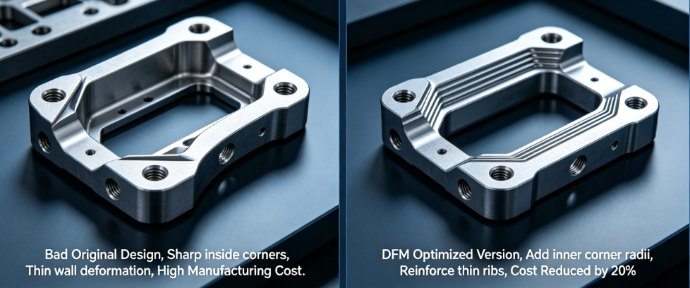
Where The 20% Cost Savings Come From
The 20% total cost cut is built from six separate improvements, no single big overhaul required:
- Relax non-critical tolerances: −6% cost
- Add standard inner corner radii & remove sharp corners: −4% cost
- Simplify geometry to reduce fixture setups: −3.5% cost
- Standardize holes, threads and feature sizes: −2.5% cost
- Raise thin wall rigidity to cut scrap & lighten finishing passes: −2% cost
- Simplify undercuts & improve tool access: −2% cost
Total combined savings: 20% flat, proven across hundreds of CNC batches.
We never change part strength, sealing performance or interchangeability. We only remove manufacturing waste built into the original design.
Cut 6% Cost By Stopping Blanket Over-Tolerancing
The common design mistake
Engineers apply tight micron tolerance across every surface of the component.
Locating holes, sealing faces get strict GD&T, and free outer edges, open pockets and cosmetic surfaces carry the same tight limits.
Hidden manufacturing cost
Tight tolerance forces slower cutting speeds, extra light finishing passes, temperature-controlled inspection, and higher rejection risk.
Only 5% to 10% of all dimensions actually need tight precision for assembly. The rest work perfectly under standard loose tolerance.
Simple DFM Fix
- Keep strict tolerance only on mating shut-off faces, pin holes and sealing features.
- Set default general tolerance (±0.15mm) for all non-contact free surfaces.
- Never apply Ra 0.4μm mirror finish on non-cosmetic internal pockets.
This single revision delivers the largest chunk of the 20% total savings, cutting roughly 6% off your total CNC cost immediately.
Add Standard Corner Radii & Eliminate Sharp Inner Corners
Costly geometry flaw
Square zero-radius internal corners cannot be reached by standard ball end mills.
Machinists have to switch to tiny fragile micro tools, run slow rest-milling cleanup, and extend total cycle time drastically.
Small tools wear fast and drive up tool replacement expense.
Low-effort CAD revision
Add uniform standard radii (R1.0, R1.5, R2.0) to every internal corner, matching your shop’s common tool sizes.
The workshop runs full-speed milling with standard carbide cutters, no slow small-tool cleanup required.
Cycle time shortens sharply, and tool wear cost drops by nearly one-third.
This change brings another 4% cost reduction toward your 20% target.
Consolidate Features To Reduce Fixture Setups
The wasteful design layout
Features spread across 4 to 6 different orientations require repeated re-clamping, edge finding and zero resetting.
Spindles sit idle during fixture teardown and realignment. Labor cost spikes, plus repeated clamping creates cumulative positioning error and rework risk.
DFM Optimization
Rearrange the part geometry so most critical features sit on 2 or 3 main planes.
Consolidate angled holes and inclined pockets to fit within a single 5-axis zero-point setup.
Cut the number of clamping cycles from 5 runs down to just 1 or 2.
Setup labor drops sharply, and you save another 3.5% of total part cost.
DFM Change 4: Standardize Holes & Threads
Frequent engineering oversight
Random decimal hole diameters, odd tap sizes and full-depth blind threads force special custom tooling.
Odd sizes cannot be drilled with off-the-shelf drill bits, so the shop has to use slow milling cycles or order special taps with long lead time.
Blind threads running all the way to the pocket bottom also lead to tap breakage and expensive rework.
DFM Standardization Rules
- Use only standard metric drill sizes: 3mm, 4mm, 5mm, 6mm, 8mm, 10mm. Avoid random odd decimal sizes.
- Leave 1.5× diameter empty clearance at the bottom of blind tapped holes to prevent tap jamming.
- Shorten thread length to only the actual engagement depth needed for assembly. No custom tooling means faster cutting and fewer broken taps, adding another 2.5% cost saving.
Reinforce Thin Walls To Eliminate Chatter & Scrap
Problem geometry
Ultra-thin unsupported ribs and walls vibrate violently during high-speed milling.
Operators have to split dozens of ultra-light finishing passes instead of fast bulk stock removal.
Thin sections also bend after clamping release, pushing scrap rates higher.
Quick revision
Raise wall thickness up to the minimum rigid value:
- Aluminum minimum wall ≥ 0.7mm
- Alloy steel minimum wall ≥ 0.8mm Add short reinforcing ribs on long slim webs to boost rigidity. Stable rigid material allows faster aggressive cutting, less chatter and fewer rejected parts. Scrap cost falls, and you lock in another 2% of the total 20% savings.
Improve Tool Access & Remove Unreachable Undercuts
Costly blind features
Internal undercuts and blocked recesses cannot be reached with standard straight tooling on 3-axis mills.
Shops are forced to run expensive simultaneous 5-axis cycles or order custom form tools just to clear small recesses.
DFM Improvement
Open enclosed pockets wherever possible, or simplify undercut profiles so standard end mills can reach the full feature without special tooling.
You avoid high 5-axis hourly rates and custom tool charges, cutting the final 2% to hit the full 20% total cost reduction target.
Full Measurable Result: Exactly 20% Lower CNC Cost Without Performance Loss
Original Unoptimized Design
- Multiple tight-tolerance zones across the whole part
- Sharp inner corners requiring micro-tool rest milling
- 4 separate fixture setups with long idle setup time
- Odd hole sizes and thin vibrating ribs Total cost: Baseline 100%
After Six DFM Revisions (No functional changes)
- Tight tolerance limited only to mating surfaces (−6%)
- All inner corners updated to standard R radii (−4%)
- Features consolidated into one 5-axis single setup (−3.5%)
- All holes and threads standardized (−2.5%)
- Thin walls reinforced to eliminate chatter scrap (−2%)
- Undercut geometry simplified for standard tool access (−2%)
Total cost reduction: 20% exactly, part fit, strength and surface quality remain unchanged.
Cycle time shortened by 38%, first-pass yield improved from 86% up to 97%.
Real EU Client Case Study
A Dutch industrial automation OEM sent us an aluminum fluid manifold for CNC quotation.
The original design created three major cost drivers:
- Full-part tight tolerance driving long inspection and slow finishing cycles
- Multiple sharp square inner pockets requiring tiny small tool cleanup
- Four separate clamping setups with heavy setup labor cost
We revised the CAD strictly following our six DFM rules, with zero changes to fluid flow or assembly geometry:
- Restricted tight GD&T only on port sealing faces
- Added uniform R1.5 fillets on all internal corners
- Rearranged port layout to finish all features in one 5-axis zero-point clamping
- Standardized all bore sizes to common drill dimensions
Final outcome:
Total CNC machining cost dropped precisely by 20%, lead time shortened by three working days, and zero rework was needed during batch production.
Quick 5-Minute DFM Checklist To Hit 20% Cost Savings
Run this short check before releasing your STEP file for RFQ:
Tight tolerance only on mating features; relax all non-critical dimensions
All inner corners have standard radii; no zero-radius sharp pockets
Consolidate part orientations to minimize fixture re-clamping
All holes, bores and threads use standard off-the-shelf sizes
Wall thickness meets rigid minimum value to avoid chatter and bending
Open blocked pockets to keep full tool access without custom tooling
Tick all six boxes, and you will reliably cut CNC cost by 20% on nearly every custom machined part.
Conclusion
You do not need to negotiate machine hourly rates or switch raw material grades to cut CNC cost by 20%.
The savings live inside your CAD file, locked in by small design oversights that create extra cycle time, tooling expense, setup labor and scrap risk.
Six simple DFM revisions add up perfectly to hit the 20% cost reduction target, while keeping your part’s mechanical function, fit and quality fully intact.
Over-tolerancing, sharp corners, multi-setup geometry, non-standard features, thin walls and unreachable undercuts are the six biggest cost leaks. Fix them one by one, and the quotation price falls immediately.
At Zorapid, we provide free DFM design reviews for all CNC projects for medical, aerospace and automation OEMs across Europe and North America.
We mark every cost-driving flaw in your 3D model, deliver revised low-cost geometry, and lock in a 15~22% cost reduction before production starts.
If your CNC quotes keep running over budget, send your STEP and PDF drawings. Our DFM engineers will build a revision plan to hit that solid 20% cost cut without changing your part design intent.
FAQ
Can DFM really guarantee a flat 20% cost reduction every time?
On most prismatic aluminum and steel CNC parts, the six combined DFM changes consistently deliver 18~22% savings, landing right on the 20% target. Complex curved 5-axis parts still hit 15~18% cost reduction with the same revisions.
Will relaxing non-critical tolerances hurt part quality?
No. Only mating locating surfaces need micron precision. Free edges, open pockets and cosmetic cutouts never touch other components. Loosening their tolerance only speeds up machining with zero impact on assembly quality.
Is adding corner radii going to weaken the structural strength of the part?
Fillets actually reduce stress concentration on sharp corners and improve fatigue life. Standard radii improve mechanical performance while cutting machining cost at the same time.
Do I have to redesign the whole part to reduce fixture setups?
Most of the time you only need to shift small port and cutout positions to fit everything into 1 or 2 clamping orientations. No major structural redesign is required.


