
Published:Zorapid.Ltd
Here’s something most designers don’t want to admit: you’re probably overpaying for CNC parts. And it’s not because your machinist is charging too much.
It’s because of your tolerances.
Tighter than they need to be. Applied to dimensions that don’t matter. Missing datums that make parts impossible to inspect.
Every year, companies waste millions of dollars on tolerances that don’t add any value. The worst part? They don’t even know they’re doing it.
If you want to cut your CNC machining costs by 20-40% without sacrificing quality or function, keep reading. We’re breaking down the most common tolerance mistakes and exactly how to fix them.
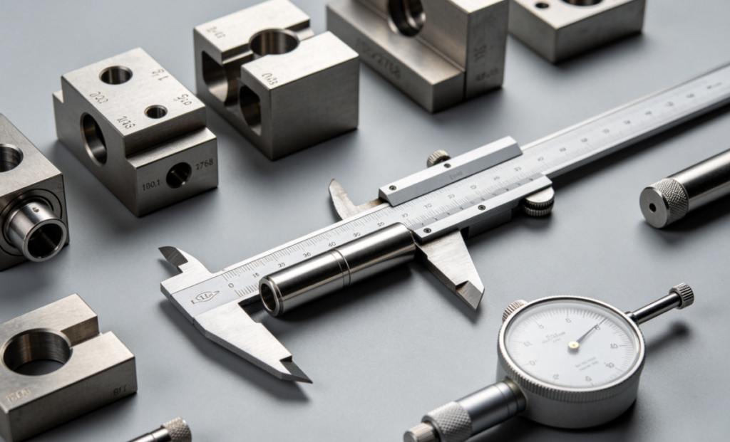
The Harsh Truth About Tolerances and Cost
Let’s start with the basics. There’s a reason machinists get twitchy when you put ±0.005mm on every dimension.
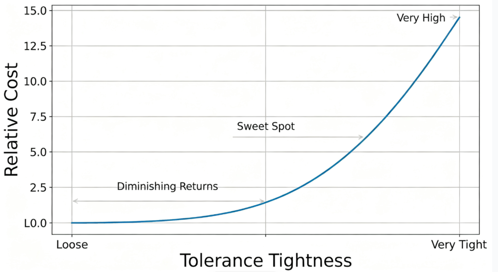
Tighter tolerances don’t just cost a little more. They cost exponentially more.
Here’s why:
- More setup time — dialing in a machine to hit tighter tolerances takes longer
- Slower feed rates — you can’t push the tool as hard if you need perfect accuracy
- More tool changes — tools wear faster, and you have to replace them before they drift out of spec
- More inspection time — every critical dimension needs CMM time, which isn’t cheap
- Higher scrap rate — more parts fall outside the tolerance band
- Better (more expensive) equipment — not every shop can hold ±0.005mm consistently
The result? A part that costs $10 with ±0.1mm tolerances might cost $30 with ±0.01mm tolerances. Same part, same material, same size — just tighter numbers on the drawing.
And here’s the kicker: most of the time, those tighter tolerances don’t actually make the part work better. They’re just there because someone copied a previous drawing, or defaulted to “precision” because it sounds better.
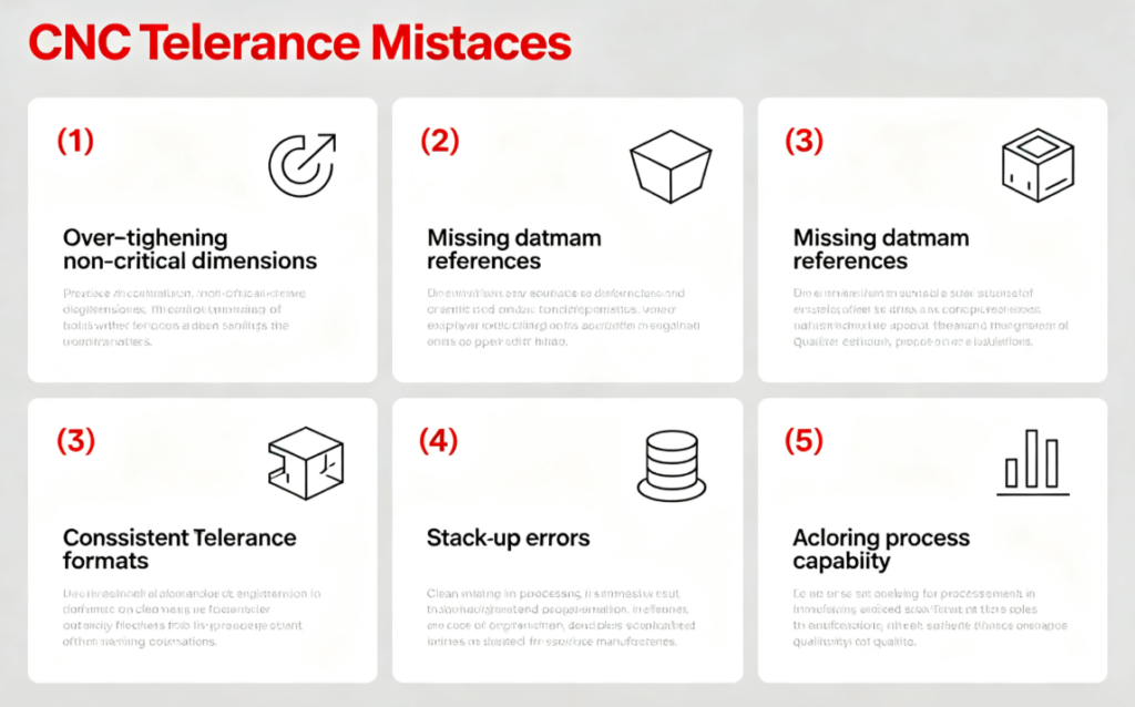
The 5 Most Common CNC Tolerance Mistakes
We see these every single day. Fix them, and you’ll save a fortune.
Mistake: Tight Tolerances on Everything
This is the big one. The mistake by a mile.
Designers see precision machining and think every dimension needs to be super tight. So they put ±0.02mm on everything. Hole positions. Overall length. Corner radii. Even features that don’t mate with anything.
Why it’s bad:
- Every tight tolerance adds cost
- Most of those dimensions don’t affect function
- You’re paying for precision you’ll never use
The fix:
Only apply tight tolerances to dimensions that actually matter. Ask yourself: “If this dimension is off by 0.1mm, will the part fail?” If the answer is no, loosen the tolerance.
A good rule of thumb:
- Critical mating features: tight tolerances (±0.01-0.05mm)
- Important but not critical: medium tolerances (±0.05-0.1mm)
- Non-critical features: standard tolerances (±0.1-0.25mm or ISO 2768-m)
Real savings: We had a customer who went from ±0.05mm on all dimensions to only critical dimensions. Cost per part dropped 35%. Functionality? Identical.
Mistake : No Datum References
You’ve seen this drawing. A bunch of dimensions with tight tolerances, but no datums. No reference points. No way to know where to measure from.
Why it’s bad:
- Different inspectors measure from different places
- You get different results depending on who checks the part
- Arguments about whether parts are in spec or not
- Machinists have to guess what you actually care about
The fix:
Define clear datums (A, B, C) on your drawing. Reference those datums for all critical dimensions. Use GD&T (Geometric Dimensioning and Tolerancing) where it makes sense.
This doesn’t just reduce arguments. It also reduces cost. When machinists know exactly what’s important, they don’t waste time holding tight tolerances on features that don’t need them.
Mistake: Tolerance Stack-Up Disasters
Here’s a classic scenario. You’ve got 5 parts in an assembly. Each has a ±0.1mm tolerance. You think the total stack-up is ±0.5mm. But in the real world, it can be way worse.
Worst-case stack-up: each part is at its maximum material condition at the same time. Suddenly your ±0.5mm assembly is off by 2mm, and nothing fits.
Why it’s bad:
- Assemblies don’t fit together
- You have to rework parts (expensive)
- Or worse, scrap whole batches (really expensive)
The fix:
- Do a tolerance stack-up analysis before you finalize the design
- Use GD&T position tolerances instead of linear dimensions where possible
- Apply tighter tolerances only to the features that drive the stack-up
- Consider “floating” one part in the assembly to absorb variation
A little time spent on stack-up analysis saves a fortune in rework. Trust us.
Mistake: Ignoring Process Capability
Here’s another one designers miss. Just because you put a tolerance on the drawing doesn’t mean it’s actually achievable — at least not consistently.
Every manufacturing process has a natural capability. CNC milling can hold certain tolerances. Grinding can hold tighter. Lapping can hold tighter still. But each step adds cost.
If you specify ±0.005mm on a milled surface, you’re not going to get it from a standard 3-axis mill. You’ll need grinding. Or maybe lapping. And that adds time and cost.
Why it’s bad:
- Your “cheap” CNC part ends up needing secondary operations
- Lead times stretch out
- Costs skyrocket
- You might get parts that technically meet spec but don’t work well
The fix:
Know what each process can realistically hold. Talk to your machinist early. Ask “can we hold this tolerance consistently with standard CNC, or do we need secondary ops?”
A good DFM review catches this before you cut a single part.
Mistake: Inconsistent Tolerance Formats
This one sounds minor, but it causes real problems.
Why it’s bad:
- Machinists and inspectors have to guess what you mean
- Misinterpretations happen
- You might get parts that don’t meet your (unstated) expectations
- Time wasted clarifying things that should be on the drawing
The fix:
Pick a standard and stick with it. Put a general tolerance block on every drawing. State the standard clearly (ISO 2768-m, for example). Only add tighter tolerances for specific critical features.
It sounds simple, but it eliminates 90% of the back-and-forth and prevents expensive mistakes.
The Tolerance Sweet Spot: How to Find It
So how do you know if your tolerances are too tight, too loose, or just right?
Here’s our proven process:
Step 1: Identify Critical Features
Go through your drawing and ask one question for every dimension: “Does this affect fit, form, or function?”
If yes → it’s critical, needs a tight tolerance.
If no → it’s non-critical, use a standard tolerance.
You’ll probably find that only 10-20% of your dimensions are actually critical. The rest can use standard tolerances.
Step 2: Apply the Right Tolerance Grade
Use these as starting points:
| Feature Type | Typical Tolerance | Notes |
|---|---|---|
| Non-critical dimensions | ±0.1-0.25mm | ISO 2768-m or -c |
| General mating features | ±0.05-0.1mm | Standard CNC capability |
| Precision fits (H7/g6, etc.) | ±0.01-0.03mm | May need grinding/honing |
| High-precision features | ±0.005-0.01mm | Grinding, lapping, or jig grinding |
| Surface finish Ra 3.2μm | Standard CNC | No extra cost |
| Surface finish Ra 0.8μm | Fine machining | +10-20% cost |
| Surface finish Ra 0.2μm | Grinding/polishing | +50-100% cost |
Step 3: Check for Stack-Up Issues
Do a quick worst-case stack-up on your assemblies. If the total variation is too high, figure out which features contribute the most and tighten those. Don’t just tighten everything.
Step 4: Get a DFM Review
Send your drawing to a trusted machinist and ask: Are these tolerances reasonable?
Can we loosen any without affecting function?
A good DFM review takes 30 minutes and can save you 20-40% on every part.
Real-World Example: 38% Cost Reduction on a Medical Device Housing
A medical device company came to us with a housing component. They were paying $85 per piece and thought that was just the cost of precision machining.
Their original specs:
- Material: 6061-T6 aluminum
- 23 dimensions at ±0.02mm
- 8 dimensions at ±0.05mm
- All surfaces Ra 0.8μm
- Annual volume: 2,000 pieces
- Cost: $85/each
Our DFM review found:
- Only 6 dimensions were actually critical for fit and function
- 17 dimensions could go to ±0.1mm with zero impact
- Most surfaces only needed Ra 3.2μm (standard mill finish)
- Only 3 sealing surfaces needed Ra 0.8μm
The optimized design:
- 6 critical dimensions at ±0.02mm (unchanged)
- 17 dimensions at ±0.1mm (loosened)
- 3 sealing surfaces at Ra 0.8μm (unchanged)
- All other surfaces at Ra 3.2μm (relaxed)
The results:
- New cost: $52.70 per piece
- 38% cost reduction
- Same functionality, same quality
- Annual savings: $64,600
And the best part? It took us 45 minutes to review the drawing and suggest the changes.
How Zorapid Helps You Save Money
Lots of shops will just make what you ask for and charge you for it. We’re different.
We actually want you to pay less. Because if you’re getting good value, you’ll keep coming back.
Here’s how we help:
Free DFM Review on Every Quote
We don’t just send you a price. We review your design and suggest changes that will reduce cost without affecting function. Tolerance optimization is a big part of that.
Transparent Pricing
We’ll tell you exactly what’s driving the cost. Is it the tight tolerances? The material? The surface finish? You’ll know, and you can decide what’s worth paying for.
Process Expertise
We know what each process can hold. We’ll tell you if a tolerance needs grinding, or if we can hit it with standard CNC. No surprises.
Quality That Doesn’t Cut Corners
Loosening non-critical tolerances doesn’t mean lower quality. It means smarter quality. We still inspect 100% of critical dimensions. We just don’t waste time inspecting things that don’t matter.
FAQ
How much can I really save by optimizing tolerances?
It depends on how over-toleranced your current design is, but 20-40% is typical. We’ve seen savings as high as 60% on parts where every dimension was unnecessarily tight. Even well-designed parts usually have 10-15% savings available.
What’s a “standard” tolerance for CNC machining?
For most CNC milled parts, ISO 2768 medium class (m) is a good default. That’s roughly ±0.1mm for dimensions up to 50mm, ±0.15mm for 50-120mm, etc. For turned parts, you can usually go a bit tighter. Critical features can have tighter tolerances called out individually.
How do I know which features are “critical”?
Ask yourself: “If this dimension is off by 0.1mm, will the part fail or not work properly?” If the answer is yes, it’s critical. If it’s just a cosmetic feature or a non-mating surface, it’s probably not critical. When in doubt, ask your machinist — we see hundreds of parts and have a good feel for what matters.
What’s GD&T and should I use it?
GD&T (Geometric Dimensioning and Tolerancing) is a system for specifying tolerances using symbols instead of just ± numbers. It’s more precise, reduces interpretation errors, and usually results in lower costs because you’re only controlling what actually matters. Yes, you should learn the basics and use it — especially for assemblies and critical features.
Can you help me optimize my existing drawings?
Absolutely. That’s one of our most popular services. Send us your drawings, and we’ll do a full DFM review including tolerance optimization. We’ll tell you what we’d change, why, and how much it would save. The review is free with any quote.
What tolerances can you actually hold consistently?
Depends on the process and feature size, but roughly:
- Standard 3-axis CNC milling: ±0.02-0.05mm
- High-precision CNC: ±0.01-0.02mm
- CNC turning: ±0.005-0.02mm
- Grinding: ±0.002-0.01mm
- Lapping/honing: ±0.001-0.005mm
These are production numbers, not lab numbers — what we can hold on every part, every day.
Do tighter tolerances always mean better quality?
No. Not even close. Tighter tolerances mean higher cost and longer lead times, but they only improve quality if the tolerance is on a feature that actually affects function. Putting a tight tolerance on a non-critical feature is just wasting money. Good engineering is about applying the right tolerance to each feature, not making everything as tight as possible.
What’s tolerance stack-up and why does it matter?
Tolerance stack-up is how individual part tolerances add up in an assembly. If you have 5 parts each with ±0.1mm tolerance, the total worst-case variation is ±0.5mm — which might be enough to make the assembly not work. Understanding stack-up helps you decide where to put tight tolerances (where they matter most) and where you can loosen them.
How does surface finish affect cost?
A lot. Standard mill finish (Ra 3.2μm) is included in the base price. Ra 1.6μm adds maybe 10%. Ra 0.8μm adds 20-30%.0.4μm or finer requires grinding or polishing, which can double the cost or more. Only specify fine finishes on surfaces that actually need them (sealing surfaces, bearing surfaces, etc.).
What’s the difference between tolerance and accuracy?
Tolerance is how much variation you allow (the ± number on the drawing). Accuracy is how close the actual part is to the nominal dimension. A part with ±0.1mm tolerance that’s within ±0.02mm is accurate and in spec. A part with ±0.01mm tolerance that’s ±0.015mm is out of spec, even though it’s more accurate than the first part.
Can you hold tighter tolerances for prototypes than production?
Yes, sort of. For prototypes, we can spend more time per part — hand-finishing, careful setup, multiple inspections. So we can hit tighter tolerances on a one-off basis. For production, you want tolerances that the process can hold consistently without extra hand work. That’s why production tolerances are usually a bit looser than prototype tolerances.
How do I get started with a tolerance review?
Just send us your drawings. We’ll do a free DFM and tolerance optimization review as part of the quoting process. We’ll show you what we’d change, why, and how much it would save. No obligation, no pressure — just honest engineering advice.
Ready to Stop Overpaying for Tolerances?
If you’re tired of:
- Paying for precision you don’t need
- Guessing if your tolerances are reasonable
- Getting parts that technically meet spec but don’t work
- Wasting money on over-engineered designs
Then let’s talk.
Send us your drawings today. We’ll review them for free, suggest tolerance optimizations, and give you a real quote with real savings.
No fluff. No buzzwords. Just better parts at a better price.
Zorapid — Smart CNC Machining, Fair Prices
3000㎡ Smart Manufacturing Center | Zhongshan, Guangdong


