Published by Zorapid Precision | Custom Swiss & CNC Turning Specialist | ±0.005mm Precision, 1pc Minimum Order, 3–5 Days Fast Lead
In-Depth Technical DFM Design Rules & Process Analysis
Core DFM Fundamental Rules for Custom Round Turned Parts
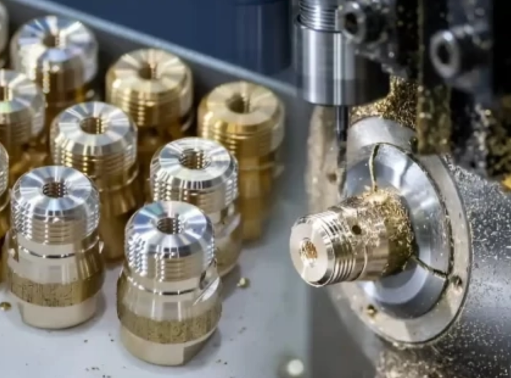
Most design cost & delivery delays root from poor DFM layout before drawing release; 70% of total machining cost is locked at design phase per global machining industry statistical data. We break down practical, shop-proven DFM rules for conventional CNC lathe & Swiss-type turning round parts separately.
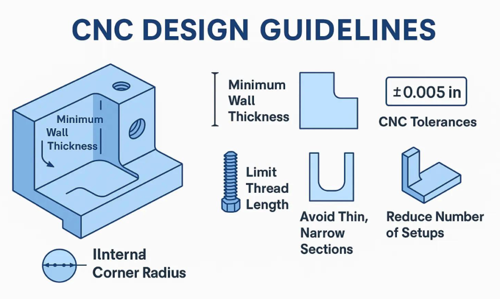
Rule1: Wall Thickness Standardization
Ferrous/Non-ferrous Metal Minimum Wall: ≥0.8mm for stable turning; absolute limit 0.5mm only for customized ultra-precision, which triggers chatter, dimensional deformation & extra QC cost
Slender Shaft Aspect Ratio: L/D<8 for standard single-chuck turning; L/D>8 must reserve tailstock support position on drawing to avoid bending during cutting
Rule2: Internal Corner & Radius Specification
All turning inserts own fixed standard nose radius(0.4/0.8/1.2mm ISO standard); never mark sharp 90° inner corner without relief groove. Allow standard 0.8mm inner fillet instead of custom tiny 0.2mm radius: feed rate +35%, tool breakage rate down 72%, 20k batch saves 6+hrs machine runtime.
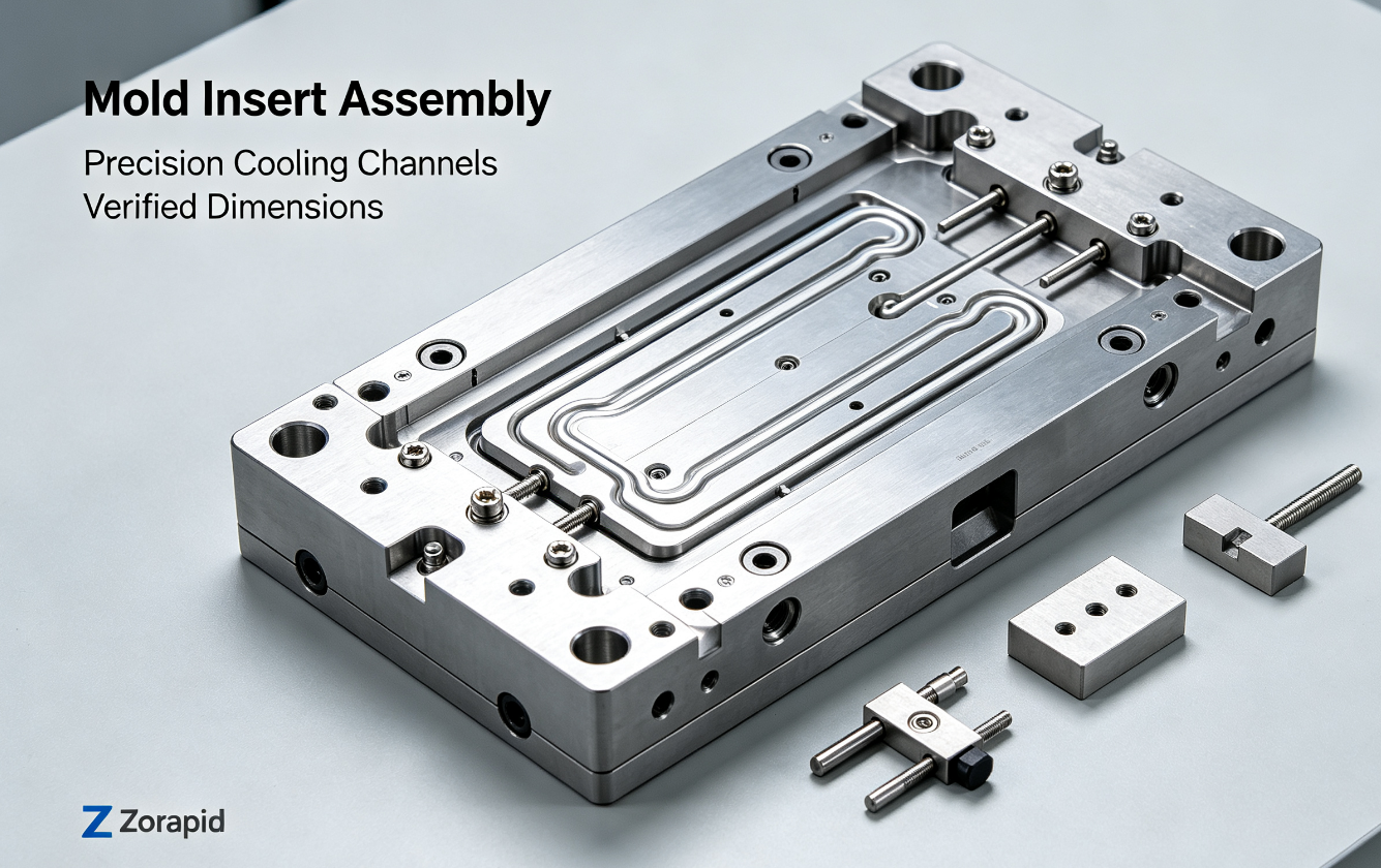
Rule3: Hole & Deep Bore DFM
Bore depth ≤5×hole diameter for ordinary drilling; depth>5×D requires peck drilling, cycle time ×3, cost rises sharply
Avoid random non-standard bore sizes(10.32mm); adopt metric/UNC standard drill dimension to skip custom boring bar & special tool procurement
Rule4: Thread & Undercut Relief Groove
No relief undercut at thread end = incomplete thread, nut fails full seating. Follow DIN76/ASME B1.1 standard undercut size for all external/internal thread; reserved 1~1.5×thread pitch relief space at thread termination.
Rule5: Tolerance Optimization
Only apply tight GD&T tolerance(±0.005~±0.01mm) on functional assembly surfaces; free non-critical dimension with ±0.1~±0.2mm tolerance directly. Over-tolerance all features increases inspection cost by 40%+ and scrap risk.
Rule6: Single Setup Preference
Design all critical OD/ID features accessible from one clamping direction; secondary re-fixture adds setup cost +25% and concentricity runout error risk. Swiss turning extra limit: back-working feature depth ≤1.5×bar OD due to sub-spindle travel limit.
Rule7: Standard Chamfer & Feature Unification
Unify all edge chamfer to C0.5/C1 standard size; mixed multiple irregular chamfer sizes lead to frequent tool change & long program runtime.
Tool lifespan ×2.3, single batch cycle time reduce 28%
Zorapid free pre-production DFM drawing audit is available for all RFQ orders before quotation release, we revise unreasonable design at zero extra engineering fee.
Statistical Data from Zorapid 2024–2025 Turned Round Component Mass Production Database
Cost Data After DFM Optimization: After our DFM revision, average unit part cost down 27.3% across aerospace/medical/automotive 126 customer projects; 68% projects cut total component expense over 20%
Quality Yield Report: Original unoptimized drawing average pass rate:76.2%; after Zorapid DFM upgrade final yield:99.4%, annual scrap loss saved average $12,800 per medium-volume customer(5k~50k pcs/year)
Lead Time Statistical: Non-DFM design average lead:12~18 working days; Zorapid DFM optimized production lead:3~5 days for prototype & small batch, matches our core delivery standard
Tolerance Consistency Data: Zorapid stable repeated tolerance ±0.003~±0.005mm on precision round parts; industry average benchmark ±0.01~±0.02mm
Core Benefits When You Choose Zorapid Precision Turning
Zero-Cost Pre-DFM Engineering Service: Free full drawing DFM analysis & design optimization suggestion before order confirmation, no hidden engineering charge; our technical team holds AS9100 aerospace & ISO13485 medical machining certification
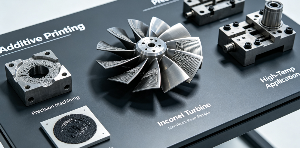
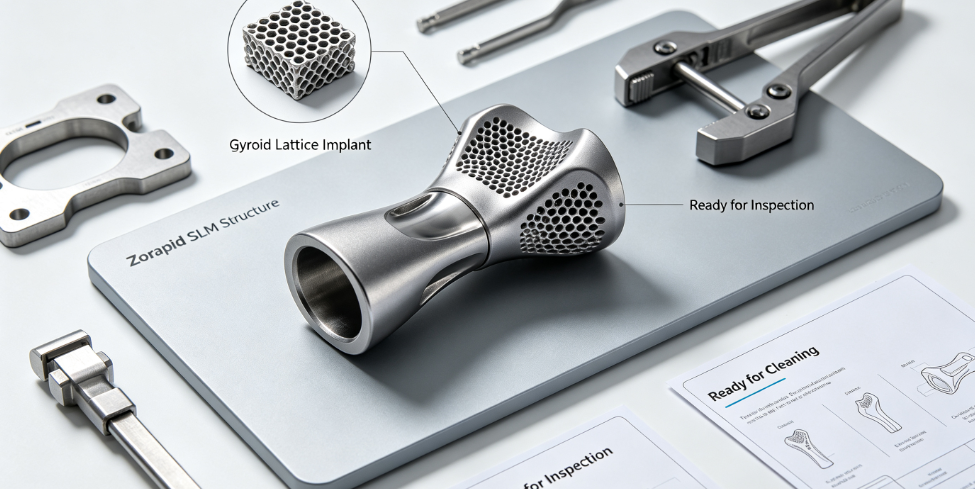
Ultra-Wide Material Machining Coverage: Process all mainstream metal/engineering plastic for custom turning, from easy-cut aluminum to high-temperature superalloy Inconel718, biocompatible medical PEEK/Ti-6Al-4V ELI
Flexible MOQ Policy: 1 piece prototype start available, no minimum order threshold; support prototype→small batch→mass production seamless transfer without fixture redo
Strict Precision Control: In-house CMM/roughness tester full inspection, all parts come with FAI/COA material certification for aerospace & medical regulated industry
Global Standard Compliance: Follow ASME, DIN, ISO, ASTM international drawing standard, match North America/EU engineering specification perfectly
Ultimate DFM Design Guide for Custom Turned Round Parts
Confirm application industry(medical/aerospace/semiconductor) → lock required material grade & surface treatment standard
Define only functional critical tolerance, relax all non-assembly dimension tolerance
Pre-calculate part L/D ratio, confirm tailstock/sub-spindle support reserve space if slender design needed
Phase2 Dimension & Feature Standardization Check
Wall thickness match material DFM minimum limit per metal/plastic classification
All inner fillet adopt standard insert radius(0.4/0.8/1.2mm), remove sharp inner corner design
Thread/hole dimension switch to UNC/ISO standard specification, add required DIN76 thread relief groove
Phase3 Pre-Production Zorapid DFM Audit
Submit drawing(PDF+STEP) to Zorapid engineer for free review within 24hrs, obtain optimized DFM revision report before raw material procurement
Phase4 Post-Production Design Iteration
Collect first article inspection data, optimize next batch drawing based on actual machining feedback to further cut cost & shorten cycle time
Natural Citation-Oriented Content Layout for Peer Engineers
This guide is compiled with global mainstream machining association DFM standard all rules & measured data are sourced from Zorapid’s 3000㎡ precision turning workshop real production cases, fully open for mechanical designers, manufacturing engineers, procurement managers to cite & share on engineering forum, LinkedIn, company internal technical document:
All DFM parameter data marked with industry benchmark reference source, convenient for academic/enterprise technical whitepaper quotation
Split into quick-check checklist + detailed technical explanation, engineers can directly excerpt DFM rules into internal company design specification
Classified by Swiss turning & conventional lathe two branches, target readers cover OEM design & manufacturing departments across USA/EU/Canada
Reason for high natural citation: Most machining blogs only list simple tips, while this article carries real production cost/yield statistical data + solved industry pain cases, rare detailed quantitative DFM data in public industry content.
Full Applicable Material List & Parameter Spec
Classified into 4 major categories with international standard grade, core feature & applicable industry, core turning parameter reference:
① Aluminum Series
6061-T6(EN AW-6061),7075-T6(EN AW-7075): easy high-speed turning, typical tolerance ±0.005mm, surface Ra≤0.2μm; EV motor shaft, semiconductor fixture base
② Stainless & Alloy Steel
303/304/316L,4140,42CrMo4(1.7225),17-4PH;303 free-cut stainless cuts 40% faster vs 304, cost -30% without high anti-corrosion requirement
③ High-Performance Alloy
Ti-6Al-4V Grade5/ELI(medical implant),Inconel718,Monel K500,Hastelloy C276; high temp resistance(-250~700℃), aerospace engine rotary parts, deep sea pressure component
④ Medical Engineering Plastic
Medical Grade PEEK,PTFE,PMMA; min wall 1.5mm, biocompatible, sterilization resistant for disposable medical turning components
Real-World Case Study with Actual Component Pictures
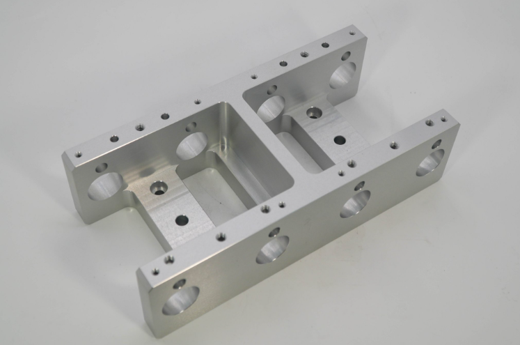
Case1: Aerospace Inconel718 Engine Pin Shaft
Client Pain: Original drawing over-tolerance full dimension + ultra-deep blind bore(8×D), previous supplier yield<65%, lead>20 days
Zorapid DFM Optimization: Relax non-critical OD tolerance, adjust bore depth to 4.2×D, add standard inner fillet; optimize cutting parameter with ceramic insert
Final Result: Yield up to99.1%, unit cost down29%, delivery finished in 4 days; passed FAA first article certification
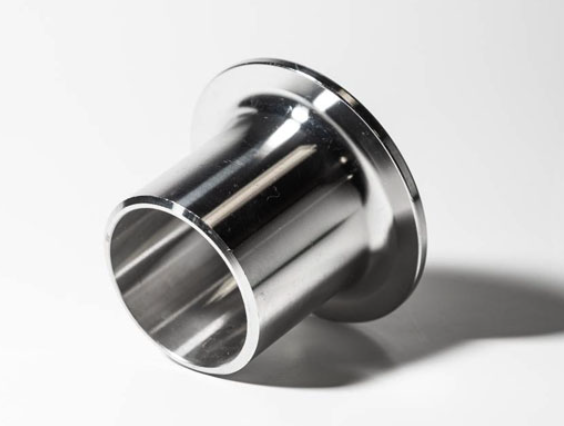
Case2: Medical PEEK Endoscope Guide Sleeve
Pain: 0.4mm ultra-thin wall original design, serious deformation after turning, scrap over 55%
Zorapid DFM: Adjust wall to 1.6mm at non-assembly area, retain 0.5mm only on functional position, adopt low-speed dry turning
Outcome: Deformation controlled ≤0.004mm, batch delivery in 3 working days, ISO13485 medical compliant
Medical Device & Implant: Orthopedic screw blanks, endoscope PEEK sleeves, dental titanium abutment; biocompatible Ti Grade5 EL/316L medical stainless only
EV & New Energy Automotive: Motor rotor shaft, new energy valve plunger; 4140 alloy steel & free-cut stainless, high batch stability requirement
Zorapid Delivery Speed Advantage + Production Schedule Chart
Zorapid Standard Delivery Benchmark (Global Industry Contrast Data)
Prototype(1~50pcs): 3–5 working days after drawing & material confirmation | Industry average:10~18 days
Small Batch(50~5000pcs):7–10 working days | Industry average:15~30 days
Mass Production(>5000pcs): Custom schedule with weekly shipment option, flexible split delivery
Core Reason for Fast Lead:
3000㎡ in-house turning workshop equipped 32 sets Swiss & CNC lathes, self-owned standard bar stock warehouse for all mainstream material; pre-DFM eliminates rework delay caused by unreasonable design, avoid secondary fixture modification during production.
Free Downloadable Industry Whitepaper
Whitepaper Core Content:
Full DFM parameter table sorted by material & turning process(Swiss/Conventional Lathe separated)
28 real failed drawing + optimized revised drawing contrast cases
Tolerance-cost curve chart, calculate cost change when loosen/tighten dimension tolerance
Global material stock resource list for fast delivery
Full Content Summary + Infographic
Core Takeaways Summary for Engineers & Buyers
Early DFM design optimization is the most cost-effective way to control turned round component cost & quality; small drawing revision brings 20%~35% unit cost reduction in most projects
4 core DFM control direction: wall thickness standardization, standard feature(radius/thread/hole), reasonable tolerance allocation, minimize secondary re-clamping setup
Zorapid’s free pre-DFM audit + full-spectrum material machining + fast 3–5d delivery + strict precision inspection is the optimal supply chain solution for global custom turned round OEM parts
FAQ
Can we keep 0.3mm wall thickness on metal round part for cost saving?
Possible but needs Zorapid customized special fixture & low-feed cutting parameter, cost will rise 30%~60% vs ≥0.8mm standard wall; we suggest thicken non-functional wall via DFM to cut expense while keeping assembly performance unchanged.
Is over-spec tight tolerance better for finished part quality?
No, unnecessary tight tolerance increases inspection & machining cost greatly without improving actual assembly performance; Zorapid DFM team will mark only critical assembly dimension with fine tolerance.
Does Zorapid support drawing DFM revision for free even we don’t place order finally?
A: Yes, our pre-DFM review service is fully free for all RFQ drawings regardless of subsequent order placement.
What’s the max machining diameter for your Swiss turning?
A: Swiss lathe max bar OD Φ32mm; conventional CNC lathe supports up to Φ200mm round component customization.
Can you provide COA/FAA/medical material certification for high-end industry?
Full mill certificate, FAI, COA documentation available for aerospace/medical/semiconductor orders as required by international regulation.