
Published:Zorapid.Ltd
If you work with Selective Laser Melting (SLM / DMLS) metal 3D printing for aerospace, medical implants, semiconductor cooling manifolds, racing motorsport hardware, or industrial tooling—you know one hard truth: as-built SLM parts are never ready for end-use straight from the powder bed.
Layer-by-layer laser melting creates extreme thermal gradients that lock in massive residual stress, trapped micro-porosity, rough stair-stepped surfaces with partially sintered powder, and mandatory sacrificial support structures. Skip or reorder any post-processing stage, and you’ll face warpage, microcracking, poor fatigue life, leaky internal channels, or failed regulatory certification (AS9100, FDA, NADCAP).
This complete guide lays out the industry-standard sequential post-processing flow for SLM metal parts, from controlled cool-down all the way to final certified packaging. We separate mandatory baseline steps from optional high-performance processes like HIP, deep electropolishing, and precision 5-axis secondary machining, plus material-specific rules, common costly sequencing errors, and a full FAQ focused on industrial and regulated medical/aerospace applications.
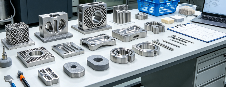
Standard Full SLM Post-Processing Step-by-Step Flow
Deviating from this order causes irreversible dimensional distortion, microcracks, or wasted secondary machining work. This is the certified SOP for ISO/ASTM 52908 additive manufacturing quality standards:
- Controlled Inert Chamber Cool-Down
- Automated Depowdering & Powder Recovery/Sieving
- On-Build-Plate Stress Relief Annealing (CRITICAL – before cutting parts off)
- Wire EDM Part Separation from Build Plate
- Sacrificial Support Removal & Rough Blend Deburr
- Pre-HIP Visual Screening + CT Porosity Check (if HIP is required)
- Optional HIP Hot Isostatic Pressing (safety-critical fatigue applications only)
- Material-Specific Solution Treatment / Aging Heat Treatment
- Precision CNC Secondary Machining (mating surfaces, threads, sealing flanges)
- Core Surface Finishing (bead blast, vibratory tumble, shot peening)
- Deep Internal Channel Cleaning (ultrasonic + high-pressure purge)
- Advanced Optional Finishing (electropolish, laser polishing, micro-peening)
- Chemical Treatment: Passivation, Anodizing, Hard Coating
- Multi-Stage NDT Inspection (XCT CT, ultrasonic, dye penetrant)
- Dimensional CMM Inspection & Surface Roughness Profiling
- Final Cleanroom Washing & Nitrogen-Sealed Packaging
Breakdown of Every Mandatory Stage: Purpose, Equipment, Key Rules
1: Controlled Inert Chamber Cool-Down
- Purpose: Prevent rapid air oxidation, thermal shock cracking, and surface contamination
- Process: After print completes, hold parts under argon/nitrogen inert atmosphere until build plate drops below 50°C (minimum 2–4hr cool cycle)
- Risk of skipping: Hot metal exposed to oxygen forms brittle oxide layers; uneven cooling spikes residual stress further
2: Automated Depowdering & Powder Recycling
- Purpose: Remove loose unsintered powder from external geometry and complex internal lattices/channels; recover reusable powder stock
- Equipment: Explosion-proof vacuum stations, closed-loop powder recovery hoppers, ultrasonic purge tanks, 15–45μm mesh sieves
- Standard workflow:
- Dry blast low-pressure compressed inert air to clear external powder
- High-pressure fluid purge to flush trapped powder out of conformal cooling channels
- Sieving to filter agglomerated oversized particles for powder reuse (>90% recovery rate for most alloys)
- Critical note: Medical/aerospace powder is single-use only; industrial non-critical parts allow controlled recycling batches
3: On-Build-Plate Stress Relief Annealing (Most Important Step)
- Purpose: Dissipate massive residual thermal stress generated during rapid laser melting; eliminates warpage/cracking when parts are cut from the plate
- Non-negotiable rule: Heat treat while parts are still fully fused to the build plate — cutting first releases locked stress and distorts geometry permanently
- Furnace: Vacuum or inert gas shielded furnace (AMS 2750 calibrated for aerospace NADCAP)
- Material baseline cycles:
- Ti6Al4V: 600–650°C, 2hr hold, slow furnace cool
- AlSi10Mg: 300°C, 2hr hold
- 316L Stainless: 550°C, 1.5hr hold
- Inconel 718: 750°C, 3hr hold
- Output benefit: Residual stress reduced by 85–95%, dimensional stability locked in for all downstream processing
4: Wire EDM Part Separation from Build Plate
- Purpose: Clean, low-stress cutting to separate parts without introducing new mechanical stress
- Why wire EDM over band saws: Zero clamping force, flat clean base surface, no material deformation, ideal for thin-wall complex geometries
- Band saw only for large, low-precision industrial non-critical bulk parts
- Post-cut step: Light surface grind to remove EDM recast layer on base datum faces
5: Sacrificial Support Removal & Rough Blend Deburr
- Purpose: Remove lattice/block support structures printed under overhangs, blend support connection points to match nominal CAD geometry
- Removal methods by geometry:
- External open supports: CNC milling, belt grinding, manual carbide burrs
- Internal channel/lattice hidden supports: Micro wire EDM, ultrasonic abrasive tumbling
- Standard requirement: Remove all support stubs down to within 0.05mm of nominal surface before finishing stages
Optional High-Reliability Stages: HIP & Special Heat Treatment
Pre-HIP CT Porosity Screening (Gatekeeping Step)
- XCT CT scan maps internal voids; HIP only closes closed isolated micro-pores (<50μm). Open interconnected voids or large lack-of-fusion defects cannot be fixed by HIP, requiring print rework first
HIP Hot Isostatic Pressing (For Fatigue-Critical Parts Only)
- Core Purpose: Simultaneous high temperature + uniform argon pressure (100–200MPa) collapses internal micro-porosity, boosting density to >99.9%, drastically improving fatigue strength and fracture toughness
- Mandatory applications: Aerospace flight brackets, medical load-bearing implants, high-cycle motorsport components
- Standard HIP cycle for Ti6Al4V: 920°C, 100MPa, 2hr hold
- Critical sequencing rule: HIP runs after stress relief, before precision CNC machining — HIP creates minor uniform shrinkage that CNC finishing corrects
Material-Specific Solution Treatment & Aging
Optimizes microstructure, hardness, ductility, and tensile strength for precipitation-hardened alloys:
- AlSi10Mg: Solution heat 540°C + T6 aging 160°C (boosts tensile strength 30%+)
- 17-4 PH Stainless: Solution treat + H900 aging for high hardness
- Inconel 718: Solution + double aging for high-temperature creep resistance
- Ti6Al4V: Beta annealing post-HIP to eliminate brittle martensite α’ phase
Precision CNC Secondary Machining Workflow
All precision machining happens after full thermal processing (stress relief / HIP / aging) — thermal cycles cause minor dimensional shift; machining last locks final tolerances
Key CNC Operations for SLM Parts
- Datum facing on EDM-cut base surfaces
- Mating sealing flange milling (target Ra ≤0.2μm for vacuum/fluid systems)
- Tight-tolerance bore reaming, counterbores, locating bosses
- Thread tapping / thread milling for assembly fasteners
- 5-axis simultaneous machining of complex angled mounting features
- Removal of HIP-induced minor surface distortion on critical datums
- Typical SLM as-built tolerance: ±0.1–0.2mm; CNC post-machining delivers ±0.002–0.01mm precision for functional interfaces
Critical Surface Finishing Options for SLM Metal Parts
As-built SLM surface roughness hits Ra 10–25μm with sharp sintered particle protrusions that act as stress risers. Choose finishing based on fatigue, fluid flow, or cosmetic specs:
- Glass Bead Blasting (Standard Baseline) Uniform matte Ra 1.6–3.2μm; removes loose sintered particles, blends stair stepping; low cost for general industrial housings
- Vibratory Abrasive Tumbling Internal lattices and hard-to-reach channels; reduces Ra to 0.8–1.6μm without damaging thin walls
- Shot Peening (Fatigue-Critical Aerospace) Compressive residual stress layer on surface; suppresses crack initiation; mandatory for high-cycle flight components
- Electropolishing (Medical Implants / Semiconductor Vacuum Parts) Dissolves surface peaks, smooths micro-valleys; Ra ≤0.1μm, low outgassing, easy sterilization; ideal for internal cooling manifolds and implant bone interfaces
- Laser Polishing (Premium High-Precision) Localized ultra-smooth finishing on small critical surfaces without altering dimensional geometry
Deep Internal Channel Cleaning & Chemical Surface Treatments
Internal Channel Purification
Critical for conformal cooling manifolds, fluid flow parts, medical fluid paths:
- Ultrasonic heated solvent bath (IPA / medical-grade detergent)
- High-pressure DI water flushing to dislodge trapped micro-powder
- Vacuum bake-out for semiconductor low-outgassing requirements (120–180°C, 12hr)
Chemical Protective Treatments (After All Machining & Finishing)
Sequence rule: Coatings/passivation run last — high-temp heat treatment destroys passive oxide layers
- Stainless Steel: Passivation (nitric acid bath) to eliminate free iron, prevent corrosion
- Aluminum AlSi10Mg: Type II clear anodize / Type III hard anodize for wear resistance
- Titanium Ti6Al4V: Medical-grade passivation, plasma coating for implant osseointegration
Multi-Stage NDT & Dimensional Inspection Protocol
Non-Destructive Volumetric Testing
- X-Ray CT Scanning (XCT): Full internal geometry scan, detect hidden porosity, lack-of-fusion, trapped powder in lattices
- Ultrasonic Testing: Large thick SLM blocks for subsurface microcracks
- Dye Penetrant Inspection (DPI): Surface crack screening for aerospace NADCAP compliance
Dimensional & Surface Metrology
- CMM Coordinate Measuring Machine: Full GD&T tolerance verification on all CNC-machined critical datums
- Surface Roughness Profilometer: Ra/Rz measurement on sealing, fatigue, and fluid surfaces
- Visual High-Magnification Optical Inspection: Support stub residue, micro-burrs, surface defects
Common Post-Processing Sequencing Mistakes That Ruin SLM Part Quality
- Cutting parts off the build plate before stress relief → severe warpage, unrepairable dimensional drift
- Running CNC machining before HIP/aging → thermal shrinkage distorts precision machined features
- Passivation/anodizing before heat treatment → high-temperature cycles erase protective surface layers
- Skipping pre-HIP CT screening → HIP cannot fix large interconnected voids, wasted HIP cost
- Support removal after precision CNC machining → grinding damage to tight-tolerance mating faces
- Depowdering after stress relief → trapped powder sinters permanently into internal channels during furnace heating
- Electropolishing before thread tapping → electro-chemical erosion shrinks thread pitch dimensions
Material-Specific Post-Processing SOP Cheat Sheet
Ti6Al4V (Aerospace / Medical Implants)
- Cool-down → depowder → on-plate stress relief (620°C)
- Wire EDM cut → support removal → CT pre-screen
- HIP (920°C, 100MPa) → beta annealing heat treatment
- 5-axis CNC machining → bead blast / shot peening
- Ultrasonic channel clean → medical passivation
- XCT NDT + CMM inspection
AlSi10Mg (Lightweight Automotive / EV Cooling Manifolds)
- Cool-down → depowder → on-plate stress relief (300°C)
- Wire EDM cut → support grind → T6 solution + aging
- CNC secondary machining → glass bead blast
- DI water channel purge → hard anodize
- DPI + CMM inspection
316L Stainless Steel (Semiconductor Vacuum Chambers / Lab Hardware)
- Cool-down → depowder → stress relief (550°C)
- EDM separation → support removal
- Optional HIP for high-cycle vacuum hardware
- CNC sealing flange machining → electropolish
- Vacuum bake-out → passivation → helium leak testing
- XCT low-outgassing certification
Inconel 718 (High-Temp Turbine Components)
- Cool-down → depowder → high-temp stress relief (750°C)
- EDM cut → support removal → CT screening
- HIP → double aging heat treatment
- CNC turbine airfoil machining → shot peening
- High-pressure channel cleaning → DPI NDT
Real-World Case: Aerospace SLM Ti6Al4V Turbine Bracket Full Post-Processing
Part Background
Flight-critical SLM Ti6Al4V turbine bracket with complex internal lattice, tight mounting hole tolerances, 10,000+ hour fatigue life requirement (NADCAP certified workflow)
Original Unoptimized Mistake
Previous batch cut parts from plate before stress relief, resulting in 0.3–0.5mm warpage, 40% scrap rate
Corrected Full Sequential Post-Processing Run
- 3hr inert cool-down, automated depowder lattice purge
- On-plate 620°C stress relief vacuum furnace hold 2hr
- Wire EDM clean separation from titanium build plate
- CNC grind external support stubs, tumble clean internal lattice supports
- Pre-HIP XCT scan confirming only isolated micro-pores present
- HIP 920°C / 100MPa / 2hr → beta annealing cycle
- 5-axis CNC machine all mounting datum holes and sealing faces
- Controlled shot peening to introduce compressive surface stress
- Multi-stage ultrasonic internal lattice cleaning + vacuum bake
- DPI crack inspection, full CMM GD&T report, XCT final volumetric certification
Measurable Outcomes
- Zero dimensional warpage, all critical tolerances held ±0.005mm
- Density raised to 99.97%, fatigue life increased 2.8x vs non-HIP batches
- 0 scrap rate, fully compliant with AS9100 / NADCAP heat treatment standards
FAQ
Why must stress relief happen while parts stay attached to the build plate?
SLM printing locks extreme tensile residual stress into the metal matrix. Cutting the part free first removes the build plate’s rigid constraint, and stress releases instantly to warp thin walls, shift hole patterns, and create microcracks. Stress relief on-plate lets the part relax uniformly without geometric distortion.
Is HIP mandatory for all SLM metal parts?
No. HIP is only required for safety-critical, high-cycle fatigue applications (aerospace flight parts, load-bearing medical implants, racing engine components). General industrial housings, static structural brackets, and cosmetic hardware skip HIP to cut cost and lead time. HIP only closes isolated closed micro-pores; large lack-of-fusion defects cannot be repaired.
Why is CNC secondary machining always the last thermal post-processing step?
HIP, solution treatment, and aging create minor uniform volumetric shrinkage across the entire SLM part. If you machine tight tolerances before heat treatment, shrinkage will push dimensions out of spec. Machining after all thermal cycles corrects shrinkage and delivers stable final dimensional accuracy.
Can electropolishing be used to smooth internal conformal cooling channels?
Yes, electropolishing penetrates deep high-aspect-ratio internal channels that bead blasting or tumbling cannot reach. It eliminates sintered powder micro-protrusions, reduces fluid flow turbulence, and delivers low-outgassing surfaces for semiconductor vacuum manifolds.
What post-processing steps are required for FDA medical SLM titanium implants?
Mandatory full flow: on-plate stress relief → EDM separation → support removal → HIP → beta annealing → CNC implant interface machining → electropolishing → medical-grade passivation → multi-stage ultrasonic cleaning → vacuum bake → XCT volumetric NDT + surface roughness certification, full batch traceability documentation.
How do I remove trapped unsintered powder from complex lattices and narrow internal channels?
Combine three steps: low-pressure inert air depowdering during initial breakout, high-pressure solvent flushing, and long-cycle ultrasonic tumbling with abrasive media. For ultra-narrow cooling channels, post-finish vacuum bake pulls residual micro-powder free from surface micro-cavities.
What’s the difference between bead blasting and shot peening for SLM surface finishing?
Bead blasting only smooths as-built stair stepping and removes loose powder for cosmetic/cleanliness. Shot peening bombards the surface with hard spherical media to create a compressive residual stress layer, drastically improving fatigue resistance for cyclically loaded aerospace parts. Shot peening is never used for cosmetic or fluid flow surfaces.
Can I skip heat treatment for low-stress static SLM aluminum brackets?
Stress relief annealing is still mandatory even for static non-fatigue aluminum parts. Unrelieved residual stress causes slow dimensional creep over temperature cycling, leading to assembly fit drift years after production. Aging/T6 treatment can be omitted for non-structural static hardware only.
What documentation is required for aerospace NADCAP SLM post-processing batches?
Full furnace temperature log charts for every thermal cycle, HIP pressure/temperature batch records, XCT CT scan reports, CMM dimensional certification, DPI/ultrasonic NDT certificates, surface roughness logs, material COAs, and wire EDM processing traceability records for full audit compliance.
How long does the complete SLM post-processing workflow take end-to-end?
Standard industrial static parts (no HIP): 4–7 business days. Aerospace/medical HIP critical parts: 10–18 business days, including thermal cycles, NDT volumetric scanning, and full certification reporting.
Quick SLM Post-Processing Production Checklist
Thermal Sequencing Checklist
Controlled inert cool-down below 50°C before depowdering
Stress relief annealing completed with parts fixed to build plate
HIP (if required) run before CNC secondary machininA
Solution/aging heat treatment executed after HIP, before finishing
AII furnace cycles calibrated to AMS 2750 / NADCAP standards
Mechanical Processing Checklist
Wire EDM used for precision part separation from plate
All support stubs blended down to nominal CAD geometry pre-finishing
CNC machining completed after all thermal shrinkage cycles
Internal channels fully purged of trapped SLM powder via ultrasonic flushing
Surface & Chemical Treatment Checklist
Fatigue-critical parts receive shot peening for compressive stress layer
Vacuum/medical components processed with electropolish low-outgassing finish
Passivation/anodizing applied as final chemical step (no post-coat heat treatment)
Vacuum bake-out completed for semiconductor low-outgassing requirements
Inspection & Certification Checklist
Pre-HIP XCT screening to rule out unrepairable large voids
Post-processing volumetric NDT (XCT / ultrasonic) performed
CMM GD&T dimensional report generated for all critical mating datums
Surface roughness profiling on sealing, fluid, and fatigue-critical surfaces
Full batch traceability COA and post-processing log packaged with finished parts
Closing Wrap-Up
SLM metal printed components cannot deliver consistent, certifiable performance without following a rigid, ordered post-processing workflow. Each stage solves a unique inherent flaw of layer-by-layer laser melting: residual stress, micro-porosity, rough surfaces, trapped powder, and dimensional instability.
Mixing up the sequence or skipping thermal treatment leads to costly scrap, failed regulatory audits, and premature part failure in aerospace, medical, EV, and semiconductor equipment. By following this standardized full flow and matching optional HIP, heat treatment, and surface finishing to your application’s fatigue, fluid, or vacuum requirements, you produce repeatable, end-use ready SLM metal parts with full quality documentation for global OEM customers.
If you need a custom post-processing SOP tailored to your SLM alloy and industry certification (AS9100, FDA, NADCAP), share your CAD material specs and performance requirements for a free optimized workflow breakdown with lead time and cost estimates.


