
Published:Zorapid.Ltd
Coated sheet metal prototypes are widely used for industrial equipment enclosures, medical device housings, automation frames, and consumer hardware NPI testing. Many design teams only focus on CAD and cutting, ignoring critical intermediate steps that cause coating failure, dimensional scrap, or long lead time delays.
This full linear workflow covers every stage from submitted CAD files to fully coated, inspection-passed prototype parts. Every step is optimized for low-volume 1–50 unit prototype batches, with clear rules to prevent common coating defects like peeling, bubbling, uneven color, or poor adhesion. The entire process is completed in-house at Zorapid to eliminate third-party outsourcing gaps and inconsistent finishing quality.
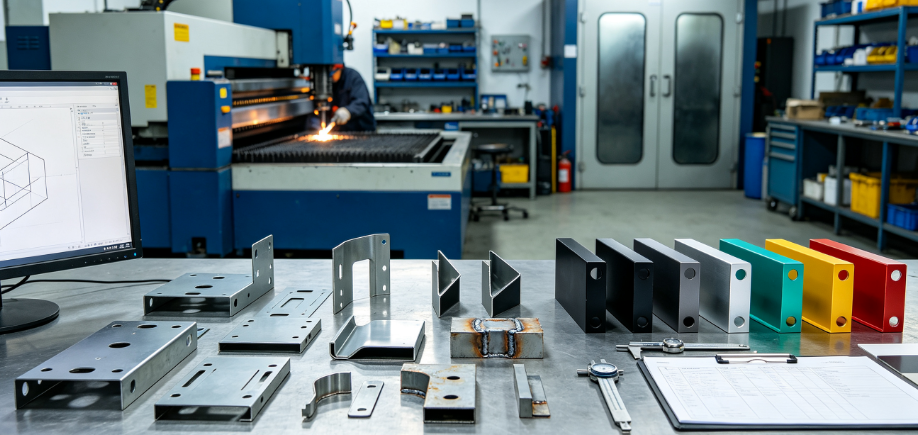
CAD Drawing Validation & DFM Optimization
All production starts with engineering review of your 3D CAD model and 2D dimensioned drawing. This stage eliminates 80% of downstream scrap risks before any metal is cut.
- File format verification: Accept STEP, IGES, SolidWorks, Fusion 360 native files; extract flat unfolded blank patterns automatically.
- Core DFM checks for sheet metal fabrication:
- Minimum bend radius matched to sheet thickness standard rules
- Hole-to-bend clearance validation to prevent tear-out during bending
- Tab & relief cut addition for tight inner corners to avoid cracking
- Wall height limits for stable CNC brake bending
- Coating-specific DFM adjustments (often overlooked by designers):
- Add 0.05–0.15 mm dimensional allowance for coating thickness on mating surfaces
- Design full drain holes to trap no cleaning/coating liquid inside closed enclosures
- Avoid blind deep pockets that trap chemical pre-treatment residue
- Annotate design revisions, coating color/texture specs, GD&T tolerances and hardware callouts on drawing
- Send annotated DFM feedback to engineers for sign-off before material ordering
Raw Sheet Stock Preparation & Nesting
Once CAD is approved, source and organize raw metal blanks matched to coating requirements:
- Material selection & stock pulling: Aluminum, cold rolled steel, stainless steel 304/316, galvanized sheet
- Aluminum: Ideal for anodizing, powder coating
- CR steel: Powder coat, liquid paint (requires phosphate pre-treatment)
- Stainless steel: Passivation, electropolish, clear powder coat
- Material segregation: Separate alloys to avoid cross-contamination that ruins coating adhesion
- CAD nesting software arranges multiple prototype parts onto one sheet to minimize material waste
- Label each sheet with part number, material grade and batch ID for full traceability
Fiber Laser Cutting for Precise Blank Profiles
High precision fiber laser produces clean blank outlines with minimal burrs, critical for uniform coating coverage:
- Load nested sheet onto laser cutting bed, fixture flat to eliminate warpage during cutting
- Laser parameters calibrated by material thickness to create smooth, low-dross edges
- Cut all outer profiles, mounting holes, slot cutouts, relief notches and drain holes in one run
- Separate finished blanks from skeleton sheet, remove small dross spatter with light brushing
- Sort blanks by part number and transfer to bending station with batch labels intact
CNC Press Brake Bending with Springback Compensation
Bending is the primary source of dimensional error if uncalibrated, and uneven bends lead to inconsistent coating thickness on corner radii:
- Import bend sequence CAM program from unfolded CAD flat pattern
- Input material thickness and alloy grade for automatic springback compensation (aluminum and steel have different rebound rates)
- Form all 90°, acute and offset bends in programmed sequence; use custom tooling for tight small radii
- In-line caliper spot checks after every 5 pieces to lock bend angle tolerance ±0.5°
- Remove sharp bend edge burrs before assembly to prevent coating pinholes later
Secondary Assembly: Welding, PEM Hardware Insertion & Deburring
Raw bent blanks require assembly and edge finishing before coating — burrs and weld spatter create coating failure points:
- Welding (TIG / spot welding for prototype frames):
- Weld joint seams ground smooth to eliminate sharp ridges that catch coating material
- Remove all weld spatter and oxidation discoloration around joint areas
- PEM nuts, standoffs, threaded inserts installation:
- Press hardware flush to sheet surface; protruding hardware creates uneven coating layers
- Full batch micro deburring:
- Vibratory media tumbling for external edges
- Manual micro finishing for internal pockets and tight corners
- Goal: Zero sharp burrs, uniform smooth surface for consistent coating adhesion
Surface Preparation (Mandatory Before Any Coating)
Poor pre-treatment is the cause of coating peeling, bubbling and short service life. This multi-stage chemical wash removes oil, oxidation, fingerprints and metal contaminants:
- Degreasing alkaline wash: Strip cutting fluid, machining oil and handling grease
- Rinse 1: Pure water flush to remove alkaline residue
- Conversion coating (material specific):
- Steel: Iron phosphate layer to boost powder paint adhesion
- Aluminum: Chromate-free conversion coat for anodizing/powder
- Stainless steel: Citric acid passivation bath
- Rinse 2: Deionized water to eliminate mineral water spots
- Oven low-temperature drying: Fully dry every crevice, drain holes prevent trapped water spots under coating
Custom Coating Application (Powder, Anodize, Paint)
Choose coating based on your prototype’s functional and cosmetic requirements; all coatings are applied after full assembly and pre-treatment:
A: Powder Coating (Most Popular for Equipment Prototypes)
- Electrostatic powder spray evenly covers all external and internal surfaces
- High-temperature oven curing to fuse powder into a hard uniform film (40–100 μm thickness)
- Available matte, satin, gloss, textured, custom RAL color matching
Option B: Hard / Clear Anodizing (Aluminum Only)
- Electrochemical anodic layer growth, controlled thickness for wear and corrosion resistance
- Dye tinting for black, silver, gold custom cosmetic finishes
- Sealing bath to lock in color and prevent oxidation
C: Liquid Industrial Paint
- Spray primer base coat + top color coat for custom low-volume color matching
- Air dry or oven cure for thin, flexible film
Option D: Stainless Steel Passivation / Electropolish
No paint layer; chemical treatment improves corrosion resistance and creates uniform metallic finish for cleanroom medical prototypes
Key coating rule: All threaded mounting holes and precision mating datums can be masked pre-coating to retain tight dimensional tolerances.
Final Dimensional & Visual QA Inspection
Coating adds uniform thickness, so full inspection validates both geometry and cosmetic quality before shipment:
- Dimensional inspection: CMM / caliper check all critical bend angles, hole positions and assembly fit dimensions
- Coating visual audit:
- No bubbles, pinholes, peeling, streaks, uneven color or exposed bare metal
- Uniform film thickness across all bends, pockets and flat surfaces
- Masked datum surfaces clean and uncoated as specified
- Adhesion cross-hatch test (random sampling per batch): Confirm coating does not peel under tape pull
- Separate non-conforming parts for rework (strip coating, re-prep and re-coat)
- Generate simple inspection log for prototype batch traceability
Clean Packaging & Batch Delivery
Coated surfaces scratch easily without protective packaging:
- Cover cosmetic exterior faces with PE protective film
- Separate individual parts with foam divider sheets to prevent coating abrasion during transit
- Bundle batch with packing slip listing part numbers, material, coating spec and inspection records
- Ship via tracked express delivery for fast NPI prototype turnaround
Real Client Case: NPI Equipment Enclosure Coated Sheet Metal Prototype Batch
An automation startup needed 15 aluminum equipment enclosures as powder coated prototypes for customer field trials.
Original Self-Sourcing Pain Points
- Designer submitted CAD without drain holes; trapped cleaning liquid caused powder coat bubbling
- No pre-DFM bend clearance check; 30% of blanks cracked during CNC bending
- Separate laser cutting shop and third-party coating vendor created misaligned batch labeling and 12-day lead time
- Unmasked threaded holes required manual post-coat tapping, damaging coating around holes
Zorapid Full In-House Workflow Solution
- DFM review added drain holes, adjusted hole-to-bend clearances and updated CAD before cutting
- Single facility completed laser cut, bending, TIG welding, deburring and full pre-treatment
- Masked all threaded holes and mounting datums prior to powder coating
- In-line bend springback calibration eliminated dimensional scrap
Final Outcome
All 15 enclosures passed visual and dimensional inspection, zero coating defects, full workflow completed in 5 business days, ready for customer prototype assembly.
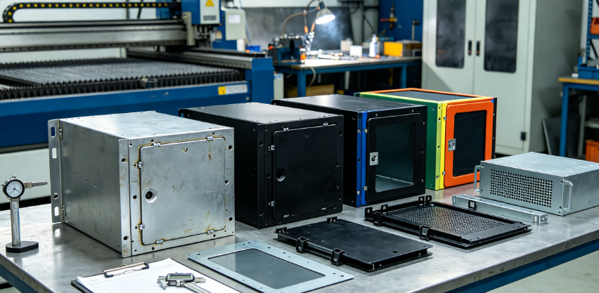
Common Workflow Defects & Fixes
- Coating bubbles / peeling Root cause: Incomplete degreasing, trapped water inside enclosures Fix: Add drain holes, extend multi-stage pre-treatment wash cycle
- Uneven coating thickness on bend radii Root cause: Sharp unground weld seams, heavy burrs blocking electrostatic powder flow Fix: Full tumble deburr + weld grinding before pre-treatment
- Bend angle out of tolerance Root cause: Missing springback compensation in CNC brake program Fix: Update CAM bend parameters by material grade, spot check after every 5 blanks
- Visible laser dross marks under coating Root cause: Uncleaned cut edges before pre-treatment Fix: Post-laser light brushing and tumble deburr stage
- Coating scratches after delivery Root cause: Insufficient protective packaging Fix: Full surface PE film + foam divider separation for all prototype batches
DFM Checklist to Avoid Coating & Fabrication Scrap
Review CAD against this list before submitting for production to cut prototype cost and delay:
- Minimum hole distance to bend line ≥1.5× sheet thickness to prevent tearing
- All closed box structures have minimum 2 mm drain holes at lowest corners
- Allow 0.05–0.15 mm coating thickness offset on all mating critical surfaces
- Internal corner relief notches added to eliminate cracking during bending
- Specify masking locations for threaded holes, precision datums and electrical contact zones
- Uniform bend radii equal to sheet thickness for consistent forming and coating coverage
- Avoid ultra-deep blind pockets that trap chemical pre-treatment fluids
FAQ
What CAD file formats are accepted to start this full workflow?
We support STEP, IGES, SolidWorks, Fusion 360, Inventor native 3D files plus 2D dimensioned engineering drawings with coating specs and tolerance notes. Our team unfolds flat patterns automatically during DFM review.
How long is the full end-to-end lead time for 1–50 coated sheet metal prototypes?
Standard turnaround: 3–6 business days covering DFM, laser cut, bend, assembly, pre-treatment, coating and inspection. Rush expedited batches can finish in 2 days for urgent NPI testing.
Can I mix multiple coating types in one prototype batch?
Yes, separate parts are labeled and routed to matching pre-treatment and coating lines, but separate pre-treatment cycles will add 1–2 days to lead time.
Why is pre-treatment non-negotiable before powder coat or anodize?
Raw metal has invisible oil, oxidation and fingerprint contaminants. Without multi-stage chemical washing, coating will bubble, peel or fail adhesion tests within weeks of prototype use.
Can masking be removed after coating without damaging the finish?
We use high-temperature resistant silicone masking tape; clean peel leaves smooth uncoated surfaces with no residual adhesive or scratch marks.
Wrap-Up
A broken split workflow (separate cutting, bending, external coating vendors) creates inconsistent quality, coating defects and extended lead times for sheet metal prototypes. This complete linear process unifies every stage under one roof, with DFM optimization upfront to eliminate most scrap risks before production begins.
From initial CAD drawing validation all the way through coated, inspected, packaged finished prototypes, Zorapid manages laser cutting, CNC bending, welding, hardware insertion, full chemical pre-treatment and multiple coating options in-house. This seamless workflow delivers consistent cosmetic and dimensional quality for low-volume NPI hardware enclosures without third-party coordination delays.
Request Your Free Sheet Metal DFM Review & Prototype Quote
Share your 3D CAD file, 2D drawing, material grade, coating specification and prototype batch quantity. Our sheet metal engineering team will complete a full pre-production DFM audit, flag coating and bending risks, and provide a transparent all-in quote covering the full end-to-end workflow.


