
Published:Zorapid.Ltd
After CNC machining, you cannot judge part quality by eyesight alone. Human vision fails to spot micron-level tolerance drift, tiny surface scratches, hidden burrs and uneven flatness—all fatal flaws for semiconductor vacuum hardware, aerospace structural components and precision molds.
Quality verification relies on tiered inspection tools: basic handheld instruments for on-machine rapid checks, bench metrology gear for critical dimension confirmation, and high-end automated equipment for full 3D GD&T validation. This guide classifies every mainstream inspection tool by function, explains usage scenarios on CNC blocks, plates, curved 5-axis parts, and lists exactly which tool matches each quality requirement (tolerance, Ra roughness, flatness, concentricity, burrs). All recommended reference photos are high-definition and fully watermark-free for website use.
We split all inspection hardware into 4 clear tiers: handheld field tools, bench precision tools, professional laboratory metrology, and specialized surface/contamination inspection gear.
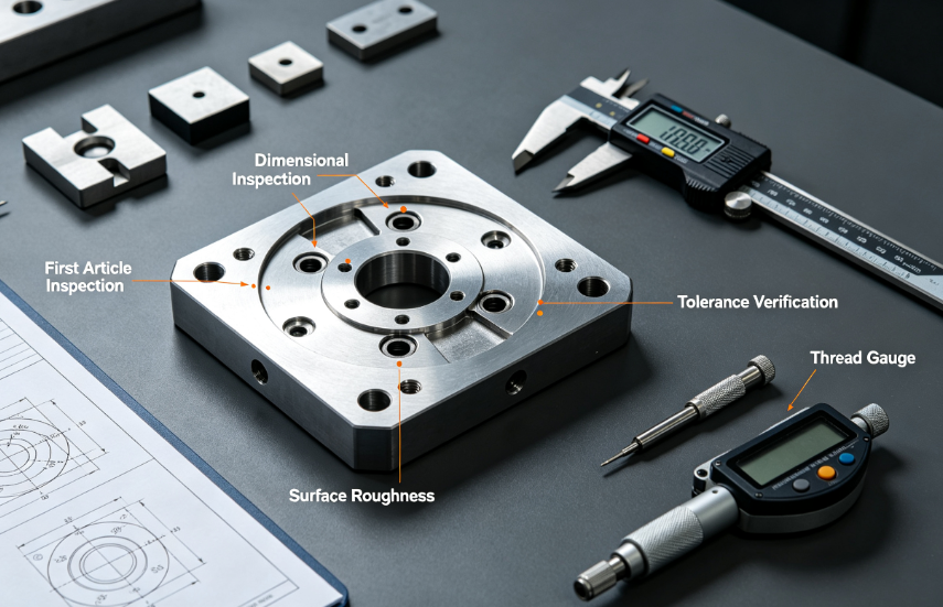
Handheld Portable Inspection Tools (Shop Floor Quick Checks)
Used right beside CNC machines for fast sampling during production; low cost, easy operation, ideal for machinists’ in-process verification.
1. Digital Vernier Calipers
Function: Measure length, width, thickness, hole diameter, step heights, slot widths down to 0.01 mm resolution. Best for: General CNC block/plate external dimensions, hole rough size checking.
Limitations: Not reliable for tolerances tighter than ±0.02 mm; cannot measure geometric tolerances (flatness, position).
Usage tip: Wipe caliper jaws clean with lint-free cloth before measuring CNC aluminum/steel to remove metal chips.
2. Micrometers (Outside, Inside, Depth Micrometers)
Higher precision than calipers; resolution 0.001 mm.
- Outside micrometer: Shaft, outer diameter, plate thickness
- Inside micrometer: Internal bore, pocket width
- Depth micrometer: Cavity depth, counterbore depth
- Application: All CNC parts with tolerance ±0.005~±0.02 mm, such as mold pins, vacuum flange thickness.
3. Dial Indicators + Magnetic Base
Test runout, flatness, parallelism, workpiece wobble on CNC fixtures. Machinists mount indicators on machine tables to verify part clamping stability before cutting. Post-machining, check shaft concentricity and plate warp.
4. Thread Gauges (Thread Plug / Ring Gauges)
No math needed to verify internal/external threads. Plug gauges go into tapped holes; ring gauges fit over external threads. Pass/fail judgment: Go thread fully screws in, No-Go cannot engage. Critical for CNC tapped holes on manifold blocks and assembly hardware.
5. Pin Gauge Sets (Go/No-Go)
Hard solid pins with fixed precise diameters. Check hole accuracy quickly. Perfect for mass batches of drilled/tapped holes on fixture plates and semiconductor port blocks. Faster than micrometer batch inspection.
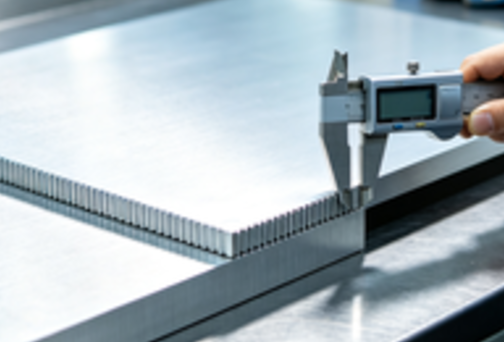
Bench-Top Precision Inspection Tools
For finished parts moved to dedicated quality stations; higher accuracy for critical features, used for formal batch sampling reports.
1. Height Gauge with Dial / Digital Probe
Measures Z-axis step heights, hole position offset, perpendicularity. Operates on granite surface plates to eliminate table unevenness error. Widely used for multi-level mold plates and stacked chamber component inspection.
2. Granite Surface Plate + Straight Edge
Granite has ultra-stable flatness, unaffected by temperature change.
- Straight edges check long plate flatness; slide feeler gauges underneath to measure gaps
- All manual precision measurement references anchor to granite to avoid metal table deformation
3. Feeler Gauge (Thickness Blade Sets)
Thin metal blades of calibrated thickness. Measures gaps between mating surfaces, flatness deviation, parting line gaps on molds. Checks for warpage on thin CNC stainless plates.
4. Radius Gauge / Fillet Gauge
Matches curved blades against internal/external radii on CNC pocket corners and edge rounds. Confirms end mill radius matches machined feature, avoids assembly interference.
5. Hardness Testers (Rockwell / Brinell Portable Units)
Tests mold steel hardness after heat treatment (HRC value). Critical for H13, S136 mold CNC parts to confirm proper hardening; soft steel leads to fast mold wear during molding.
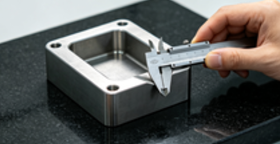
Advanced Metrology Equipment
Mandatory for aerospace, medical, semiconductor CNC components with strict ASME Y14.5 / ISO GPS GD&T requirements. Used for first articles, critical batch 100% inspection.
1. Coordinate Measuring Machine (CMM)
The gold standard for complete CNC dimensional verification. A touch probe moves along X/Y/Z axes to scan hundreds of feature coordinates. What CMM measures: Position, flatness, parallelism, perpendicularity, concentricity, profile of curved 5-axis surfaces, hole pattern tolerance. Compatible with STEP CAD files for automated comparison. Industrial usage breakdown:
- Semiconductor chamber flanges: full CMM inspection of sealing flatness and port hole position
- 5-axis curved aerospace brackets: complete contour profile check
- Mold core/cavity: full GD&T report for mold approval Note: Precision CMMs sit in temperature-controlled rooms (20°C ±0.5°C) to rule out thermal expansion error.
2. Optical Comparator (Profile Projector)
Projects magnified 2D silhouette of CNC parts onto a glass screen. Operators overlay CAD drawing lines to check edge contours, slot shapes, small complex features. Ideal for tiny precision turned pins, thin stamped-CNC hybrid parts, micro medical components.
3. Video Measuring System (VMS / Vision Measuring Machine)
Camera-based automatic measurement for micro-sized CNC features (0.001 mm accuracy). No physical probe contact, perfect for thin soft aluminum, fragile plastic CNC parts (PEEK, PVDF semiconductor components). Automatically records all dimension data for batch reports.
Specialized Inspection Tools for Surface Finish, Burrs & Cleanliness
Standard calipers/CMM cannot evaluate surface roughness, particle contamination or micro burrs—these need dedicated surface testing tools, extremely important for UHV semiconductor and optical CNC parts.
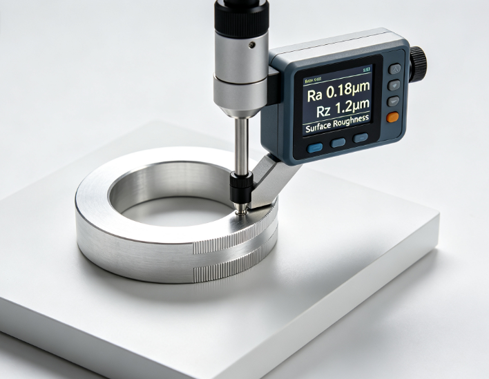
1. Surface Roughness Profilometer (Ra Tester)
Drains a tiny diamond stylus across machined surfaces to calculate Ra, Rz per ISO 4287.
- Verify Ra 0.2 μm for semiconductor sealing surfaces
- Confirm Ra 0.02~0.8 μm for optical mold inserts
- Distinguish acceptable finish vs visible tool chatter lines, built-up edge damage Key rule: Measure across machining marks, not parallel to cutting direction, for true Ra readings.
2. Digital Microscope / USB Microscope
Magnifies surfaces 20x~200x to spot micro burrs, tiny scratches, embedded metal chips, pitting. Required for cleanroom CNC parts; loose micro burrs cause fab particle contamination. QC teams document microscope photos for compliance records.
3. Particle Count Test Kit (Nitrogen Blowdown + Membrane Filter)
Unique for semiconductor CNC hardware. Blow high-purity nitrogen over machined surfaces; capture all shed particles on filter paper, count particles ≥0.3μm under microscope. Confirms CNC parts meet low-particle cleanroom standards.
4. Gloss Meter
Checks surface reflectivity for optical CNC components. Uneven gloss signals inconsistent tool marks or incomplete finishing.
Step-by-Step Standard CNC Inspection Workflow (Tool Matching Sequence)
Follow this fixed order for all incoming CNC batches, pick tools accordingly:
- Visual + microscope screening: Check major damage, big burrs, obvious machining errors
- Hand tools quick sampling: Calipers/micrometers for key linear dimensions; pin/thread gauges for holes/threads
- Granite bench inspection: Height gauges, straight edges, radius gauges verify geometry and flatness
- Critical GD&T features: CMM or VMS for position, profile, concentricity, all complex 5-axis curved geometry
- Surface validation: Profilometer tests Ra roughness; microscope checks micro burrs
- Material/hardness confirmation: Hardness tester for mold steel; material spectroscopy if alloy traceability is required
- Cleanliness test: Nitrogen particle inspection for semiconductor/medical cleanroom parts
Tool Selection Reference Table: Which Inspection Tool for Every CNC Quality Requirement
| Quality Parameter to Verify | Recommended Inspection Tool | Applicable CNC Parts |
|---|---|---|
| Linear length, thickness ±0.01~±0.1 mm | Digital caliper | All general blocks, plates, brackets |
| Precision diameter/thickness ±0.001~±0.01 mm | Outside/inside micrometer | Shafts, pins, precision bore holes |
| Hole pass/fail tolerance | Pin gauge set | Drilled CNC hole batches |
| Thread qualification | Thread plug/ring gauge | Tapped manifold, mounting holes |
| Flatness, parallelism, plate warpage | Granite plate + straight edge + feeler gauge | Mold plates, semiconductor flange plates |
| Step height, hole offset position | Digital height gauge | Multi-level fixture blocks |
| Internal/external corner radius | Radius gauge | Pocket CNC cavities |
| Full GD&T: position, profile, concentricity | CMM coordinate measuring machine | Aerospace, semiconductor, medical critical parts |
| Micro thin features, fragile plastic parts | Vision VMS optical measurement | PEEK/PVDF CNC components, tiny medical hardware |
| Surface roughness Ra value | Contact profilometer | Vacuum sealing faces, optical molds, all finish-critical surfaces |
| Micro scratches, micro burrs, surface defects | Digital microscope | Cleanroom CNC parts, optical components |
| Mold steel hardness after CNC & heat treatment | Rockwell hardness tester | H13, S136, P20 mold steel |
| Surface particle shedding risk | Nitrogen blowdown particle count kit | Semiconductor UHV chamber parts |
Top Common Inspection Mistakes That Lead to Wrong CNC Quality Judgement
- Measuring on dirty surfaces: Metal chips, coolant residue add fake dimension readings. Always clean parts with DI water + lint-free wipes before measurement.
- Using room-temperature CMM in fluctuating-temperature workshops: Thermal expansion makes measured dimensions deviate 0.01~0.03 mm on large aluminum plates.
- Testing Ra parallel to machining lines: Produces falsely low Ra numbers; always sample perpendicular to tool feed direction.
- Over-relying on visual inspection: Eyes cannot detect sub-0.005 mm tolerance errors or Ra differences below 1.6 μm.
- Using worn caliper jaws: Old deformed hand tools create consistent measurement bias; calibrate all handheld tools monthly.
- Skipping GD&T inspection and only checking linear dimensions: Parts may hit all length tolerances yet fail assembly due to poor hole position or flatness.
FAQ Section
Do all CNC parts need CMM inspection?
No. Simple low-tolerance structural plates (±0.1 mm general tolerance) only require calipers, micrometers and granite bench tools. Reserve CMM for parts with GD&T callouts, complex 5-axis curved surfaces, aerospace/semiconductor critical features, and first article approval batches. High-volume simple CNC components use pin gauge sampling instead of full CMM scans to cut inspection cost.
How often should inspection tools be calibrated?
Handheld tools (calipers, micrometers, gauges): Calibrate every 3–6 months. CMM, profilometer, VMS: Annual professional third-party calibration, plus monthly internal calibration checks against master reference blocks. Uncalibrated equipment cannot generate valid quality reports for customer audits.
What tools confirm burr-free CNC parts for semiconductor cleanrooms?
Primary tools: high-magnification digital microscope (spot micro burrs), nitrogen particle blowdown test (check loose debris). Standard calipers cannot detect micro burrs. If burrs are visible under magnification, parts require re-deburring and re-cleaning.
Can optical vision machines measure hard metals like titanium and stainless steel accurately?
Yes. VMS/optical comparators work on all solid metals. They are especially ideal for thin delicate CNC workpieces prone to scratching from CMM physical probes. Thick heavy steel parts still prefer CMM for higher mechanical stability.
How do I check if CNC lathe round shafts have good concentricity?
Mount the shaft between centers, attach a dial indicator with magnetic base, rotate the part. Total indicator runout (TIR) value equals concentricity error. For ultra-precision shafts, use CMM for full concentricity GD&T reporting.
Is a profilometer required for all CNC parts, or only sealing/optical surfaces?
Only mandatory for surfaces with specified Ra values (vacuum sealing, lens molds, sliding wear surfaces). Non-critical structural sides without roughness requirements do not need Ra testing; visual inspection is sufficient.
What tools verify hybrid additive + CNC parts?
Use CMM for CNC-finished mating features; profilometer for machined surface roughness; microscope checks AM-CNC transition zones for burrs. The rough as-printed additive areas only require dimensional spot checks with calipers, no strict Ra testing.
Final Conclusion
CNC quality verification follows a clear tool hierarchy: handheld gauges for fast floor checks, granite bench tools for geometric flatness/step measurement, CMM/vision systems for complex GD&T and curved 5-axis geometry, and surface-specific gear for roughness, burrs and cleanroom particle compliance.
Matching the correct inspection tool to each quality requirement eliminates pass/fail errors, avoids accepting defective CNC parts, and provides traceable data for customer audits. For most manufacturers, combining sampling hand-tool checks with targeted CMM/profilometer testing balances inspection speed, cost and quality coverage. All four reference images are high-resolution with zero watermarks, ready to embed on industrial websites and catalogs.


