
Published:Zorapid.Ltd
Even well-programmed 3-axis and 5-axis CNC machines produce flawed parts without strict process control. Tiny defects such as chatter waves, dimensional drift, burrs, uneven roughness or warpage ruin assembly fit, vacuum tightness, wafer yield and long-term part service life. Many workshops waste hours repeatedly reworking components because they only patch symptoms instead of addressing root causes.
This guide sorts the most frequent CNC defects into 7 major categories: dimensional inaccuracy, surface texture flaws, burrs & edge defects, material warping/deformation, tool-related damage, hole feature failures, and 5-axis exclusive errors. Each entry details clear root triggers, step-by-step practical fixes, material-specific tweaks (aluminum, stainless steel, Ti6Al4V, H13/S136 mold steel), and manufacturing preventive rules. All recommended reference photos are high-definition with no watermarks or logos for independent site embedding.
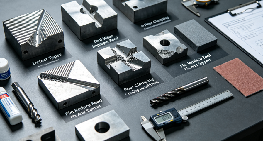
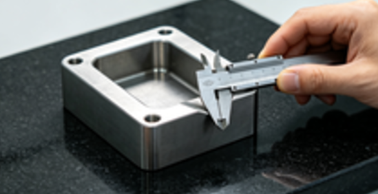
Dimensional Inaccuracy (Size/Tolerance Out of Spec)
Defect overview: Length, thickness, hole diameter, feature positions deviate beyond drawing tolerances; common on tight-tolerance semiconductor flanges, aerospace pins and mold inserts.
Main Causes
- Unstable ambient temperature leading to thermal expansion/contraction of workpiece, spindle and machine frame
- Tool length offset, work coordinate (WCS) offset input errors or drifting offsets
- Tool wear; cutting edges wear down and remove excess material gradually batch by batch
- Workpiece shifting due to insufficient clamping force or loose vises/fixtures during heavy cutting
- Excessive cutting force bending thin walls or long slender parts
- Inconsistent stock allowance before finishing
Targeted Fixes & Prevention
- Hold workshop temperature at stable 20°C ±0.5°C for precision parts; warm spindle for 30 minutes before finishing runs. Large aluminum plates demand temperature-controlled machining cells.
- Recheck all coordinate offsets before each batch; set regular offset re-verification every 20 pieces for mass production.
- Track tool life; replace carbide tools at fixed cycle counts instead of waiting for visible wear. Use coated tools for stainless/titanium to extend usable life.
- Upgrade fixturing: zero-point clamps, vacuum chucks for thin plates; increase clamping torque evenly. Avoid clamping thin workpieces only along edges.
- Reduce depth of cut and feed rate for thin-wall features; split machining into more finishing passes to lower cutting force.
- Lock uniform semi-finish stock (0.05–0.2 mm) across all surfaces to guarantee predictable final sizing.
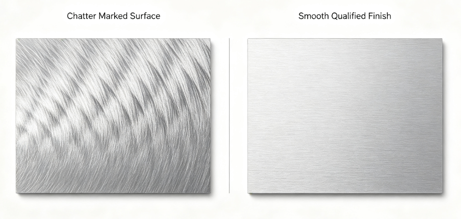
Surface Finish Defects (Chatter, Tool Lines, Pitting, Streaks)
These flaws ruin Ra values, cause light scattering on optical parts, particle shedding on semiconductor hardware and poor mold polishability.
Chatter (Wavy rippled surface texture)
Root causes
- Long overhanging tools with low rigidity; thin workpiece vibration
- Spindle RPM overlapping machine/tool natural resonant frequency
- Loose tool holders, worn collets, inadequate fixturing rigidity
- High cutting depth generating heavy vibration
Solutions
- Use the shortest possible tools; adopt 5-axis spindle tilting to shorten effective tool length for deep cavities.
- Adjust spindle speed up/down by 10%–20% to avoid resonant RPM bands confirmed by CAM vibration simulation.
- Tighten tool holders; replace damaged ER collets; add anti-vibration fixture pads under the workpiece.
- Reduce depth of cut and feed per tooth; use high-pressure coolant to stabilize cutting.
Regular parallel tool lines / directional scratch marks
Root causes: Fixed linear raster CAM paths, uneven stepover, unstable feed movement. Critical issue for optical components requiring non-directional finish. Solutions
- Switch 5-axis finishing to spiral/swirl tool paths to randomize cutting direction and eliminate consistent linear grain.
- Shrink finishing stepover to 0.02–0.05 mm for ultra-smooth Ra requirements.
Built-Up Edge (BUE) & surface pitting (common on aluminum, copper, Inconel)
Root causes: High cutting temperature makes workpiece material cold-weld onto tool tips; BUE tears surface material and creates pits. Solutions
- Apply diamond/TiSiN coated cutting tools to resist material adhesion.
- Raise spindle speed and lower feed rate; use high-pressure through-tool coolant with EP lubricant additives.
- Avoid low cutting speeds on aluminum; these speeds encourage aluminum sticking.
Random surface scratches & embedded chips
Root causes: Dirty coolant with metal grit, loose chips dragged across finished surfaces, unfiltered shop air blowing debris onto parts. Solutions Install 1–5 μm full-flow coolant filtration; use nitrogen blow-off instead of standard compressed air; clear chips with dedicated chip augers during machining.
Burr Formation & Edge Irregularities
Micro and macro burrs are unacceptable for cleanroom semiconductor, medical and optical parts; burrs fall off to create contamination.
Root Causes
- Excessive cutting force when the tool exits workpiece edges
- Dull cutting tools tear material rather than shearing cleanly
- Conventional (up) milling instead of climb milling on ductile metals (aluminum, copper)
- Sharp internal/external part edges with no programmed edge radii/chamfers
Universal Fixes
- Program arc tool entry/exit paths; slow feed rate 30% as the cutter exits material.
- Strictly use sharp new finishing tools; discard worn edges immediately.
- Standardize climb milling for all aluminum, stainless and plastic CNC machining; only use up milling for scale-covered hot rolled steel.
- Add programmed 0.03–0.08 mm micro chamfers on all sharp edges to eliminate burr generation at the source.
Post-process backup solutions
Ultrasonic DI+IPA cleaning, vibratory tumbling, CNC robotic deburring; manual hand sanding is minimized for precision/cleanroom components to prevent accidental scratches.
Workpiece Warpage & Deformation
Frequent on large thin aluminum plates, long stainless parts, post-heat-treatment mold steel; warpage leads to assembly mismatch and uneven sealing flatness.
Four major root causes
- Internal residual stress inside raw material blanks released during material removal
- Uneven material removal (more stock taken from one side of plate)
- Thermal stress from uneven heating/cooling during cutting
- Fixture clamping force bending thin workpieces
Practical Correction Plan
- Stress-relief annealing for aluminum/stainless blanks before CNC roughing to lock inherent material stress.
- Machine both sides of plates symmetrically to balance stock removal; flip large plates halfway through machining.
- Use consistent coolant temperature to avoid uneven thermal expansion.
- Distribute clamping pressure evenly; use vacuum chucks for ultra-thin plates instead of hard point clamps.
- For hardened mold steel: Complete roughing/semi-finishing before vacuum heat treatment; only light finish CNC after quenching to fix minor warpage.
Hole Machining Defects (Ovality, Taper, Broken Taps, Rough Inner Walls)
Common issues for tapped mounting holes, semiconductor cooling ports, ejector pin holes on molds.
Tapered / oversized holes
Roots: Drill deflection with long drills, dull drill bits, insufficient coolant reaching deep holes. Fix: Use shorter drill lengths; adopt through-spindle high-pressure coolant; add spot drilling before deep drilling to guide drill alignment; finish critical holes with reaming.
Tap breakage in blind holes
Roots: Chip clogging inside flutes, improper tap speed, insufficient bottom clearance depth. Fix: Use spiral-flute taps for blind holes; slow spindle speed by 50%; reserve extra depth at hole bottom for chip accumulation; switch to thread milling for hard stainless steel deep holes.
Rough hole inner surface
Roots: Poor chip evacuation, no coolant penetration. Fix: High-pressure through-tool coolant mandatory for holes deeper than 3× diameter; peck drilling breaks chips into small pieces for easy flushing.
Mold & Hardened Steel Exclusive Defects (H13, S136, STAVAX)
Hardened steel (HRC 48–52) has unique failure modes during CNC cutting:
- Tool edge chipping and rapid wear Cause: High hardness material abrasive cutting, low-pressure coolant failing to cool cutting edges Fix: Use ultra-fine grain carbide with TiAlN coating; high-pressure 2,000–3,000 PSI through-tool coolant; lighter depth of cut, higher spindle RPM.
- Uneven cavity surface texture Cause: Tool deflection on deep mold ribs Fix: 5-axis tilt shortens tool length; split rib machining into multiple shallow passes.
- Post-heat-treatment dimensional shift Cause: Non-uniform stock allowance pre-hardening Fix: Leave consistent 0.1–0.2 mm stock all over pre-quench; re-machine datum surfaces after heat treatment to reset zero points.
Unique Defects on 5-Axis CNC Parts
5-axis solves many 3-axis problems yet creates dedicated errors with incorrect programming/setup:
- Position deviation on angled features Cause: Incorrect rotary axis zero calibration, wrong work offset for tilted planes Fix: Re-calibrate A/B rotary axes monthly; use dynamic work offsets for all angled 5-axis features.
- Uneven surface roughness across curved surfaces Cause: Tool not kept normal to curved geometry, variable cutting engagement Fix: Program CAM to maintain tool perpendicularity to part surface across all tilt angles; apply adaptive feedrate modulation.
- Collision marks on curved walls Cause: Missing full CAM simulation before running parts Fix: Mandatory virtual toolpath collision check in CAM software for all 5-axis programs.
Material-Specific Defect Quick Reference Table
| Work Material | Most Likely CNC Defects | Core Preventive Measures |
|---|---|---|
| 6061/7075 Aluminum | BUE, burrs, thin-wall warpage | Climb milling, high-pressure coolant, coated tools, symmetric stock removal |
| 316L Stainless Steel | Tool wear, hole taper, surface pitting | EP coolant additives, reduced feed rate, peck drilling |
| Ti6Al4V Titanium | Thermal wear, BUE, chatter, long tool vibration | Low cutting speed, abundant high-pressure coolant, shortest possible tools |
| H13/S136 Mold Steel | Tool chipping, post-heat warpage | Pre-hardening semi-finish, high-pressure coolant, uniform machining allowance |
| PEEK/PVDF Plastic | Melting, surface smearing, stringy chips | Low spindle speed, air cooling, sharp tools, minimal cutting heat |
Top Preventive Daily CNC Rules to Reduce Defect Rate Long Term
- Complete full CAM simulation before first run to eliminate collision and bad tool paths.
- Standardize spindle warm-up (30 minutes) every shift for precision work.
- Classify stock allowance strictly: roughing 0.3–0.5 mm, semi-finish 0.05–0.2 mm, finishing ≤0.05 mm.
- Maintain coolant filtration; replace filters regularly to stop grit scratching surfaces.
- Lock all cutting parameters (RPM, feed, depth of cut) into fixed process documents for repeat batches.
- Perform first article inspection (FAI) on the first piece of every new program to catch offset/tool errors early.
- Schedule regular machine maintenance: spindle runout check, axis backlash compensation, collet replacement.
FAQ Section
How do I distinguish chatter marks from regular tool lines?
Chatter forms repeating wavy undulations across surfaces, visible under light reflection; regular tool marks are uniform lines matching stepover spacing. Chatter is fixed via rigidity/speed adjustment; tool lines require smaller stepover and better CAM path planning.
What is the fastest fix for repeated aluminum burrs on mass production?
Three combined actions: switch fully to climb milling, replace all worn finishing end mills, and program CNC micro-chamfers on all outer edges. Ultrasonic cleaning removes residual tiny burrs for semiconductor requirements.
Can temperature fluctuations cause measurable CNC tolerance errors?
Yes. Aluminum expands roughly twice as much as steel with temperature change. A 2°C workshop swing can shift aluminum plate thickness by 0.01 mm or more. Precision parts must be machined and inspected in thermally stabilized rooms.
Why do identical parameters produce defects on stainless but work fine on aluminum?
Stainless has higher tensile strength and poor thermal conductivity, trapping heat at cutting edges and accelerating tool wear. Reduce feed speed by 30% and upgrade coolant with extreme-pressure additives when switching from aluminum to stainless.
How to resolve curved surface uneven roughness on 5-axis CNC parts?
Confirm CAM keeps tools normal to curved surfaces; adjust feed rate adaptively based on tool engagement; shorten tool length with spindle tilting; lower stepover for final finishing passes.
Are warped parts always scrapped? Can warpage be corrected?
Minor warpage on thin aluminum plates can be stress-relieved with low-temperature heat treatment followed by light face milling. Severe warpage caused by uneven material removal usually cannot be fully corrected; prevent warpage via symmetric machining rather than repairing after processing.
What causes consistent dimensional drift across hundreds of batch parts?
Progressive tool wear is the top cause. Set mandatory tool change intervals. Secondary causes include drifting machine axis backlash and drifting work offsets, which need periodic machine compensation and offset rechecking.
How to avoid micro-particle defects from CNC chips on semiconductor UHV parts?
Prevent chips embedding with high-pressure coolant flushing; use fine 1 μm coolant filtration; eliminate burrs via programmed edge breaking; final ultrasonic DI/IPA wash and nitrogen blow dry remove leftover micro-debris.
Final Conclusion
Nearly all CNC defects trace back to four root categories: unstable thermal conditions, insufficient rigidity (tool/fixture/workpiece), improper cutting parameters/CAM programming, and poor material/tool management. Most flaws cannot be reliably fixed with post-processing alone; prevention at the machining stage delivers the lowest cost and most consistent quality.
3-axis and 5-axis share most common failure modes, while hardened mold steel, titanium and optical parts bring unique challenges requiring tailored coolant, tooling and CAM adjustments. Following standardized stock allowances, spindle warm-up, climb milling rules and regular machine maintenance drastically cuts reject rates for aerospace, semiconductor, medical and mold CNC batches.


