
Published:Zorapid.Ltd
If you’re a product engineer, procurement manager, or startup founder launching plastic parts for automotive, medical, consumer electronics, or industrial hardware—you’ve almost certainly hit these headaches:
- Parts warp, sink, or develop ugly weld lines after mold trials
- Tool lead times stretch 2+ months, killing your time-to-market
- Hidden mold revisions pile up thousands in extra costs
- Molds wear out fast with frequent maintenance downtime
- Suppliers skip critical simulation, handing you untested steel
This full handbook from Zorapid breaks down every single stage of injection mold design and manufacturing, plainspoken with zero overly complex jargon. We built it specifically for Western OEM teams: we follow ISO, ASME and EU medical manufacturing standards, and every tip comes from 20+ years delivering production-grade molds to North America, UK, Germany, France and Nordic brands.
We’ll walk you through DFM pre-checks, mold structural design rules, steel material matching, Moldflow simulation, full mold machining workflow, T1-T3 trial standards, mass production optimization, and how to pick a reliable tooling partner that avoids costly rework. No fluff—only actionable, factory-proven rules you can plug straight into your next project.
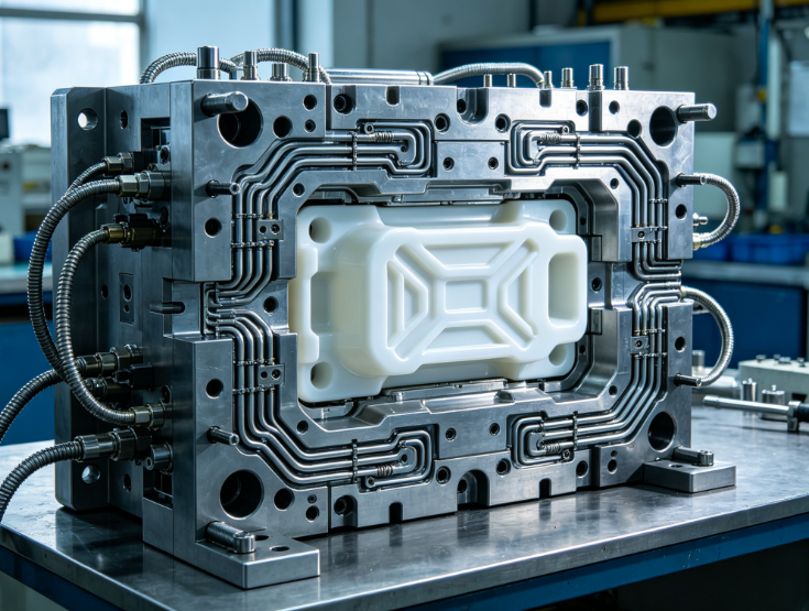
Why Mold Design Makes Or Breaks Your Entire Injection Molding Project
Let’s get one hard truth out first: your plastic part quality, production speed, long-term per-unit cost, and mold lifespan all live or die at the mold design phase.
Lots of overseas tool shops just import your CAD file, mill a cavity, and ship the mold without deep design engineering. For small hobby parts this might slide—but for commercial OEM products targeting EU/US markets, this shortcut creates massive downstream losses:
- Uneven cooling adds 10–40 seconds to every cycle, blowing your mass production profit margin
- Poor gate placement creates visible weld lines that fail cosmetic inspection
- Weak venting traps air, burning part surfaces and causing dimensional drift
- Thin rib ratios or zero draft angles lead to stuck parts, frequent ejection damage
- Cheap steel without proper heat treatment wears out after 50k shots, forcing early mold replacement
At Zorapid, we treat mold design as risk mitigation, not just drawing steel shapes. Every design round ties back to your production volume, resin type, cosmetic class, tolerance specs (±0.02mm precision standard for our EU clients), and long-term run goals. A small investment in robust design cuts total project spend by 25–40% over the mold’s full service life.
DFM Analysis – The Non-Negotiable Pre-Design Stage
Before we draw a single mold 3D model, our engineers run a full Design for Manufacturability report and send it to your team for review—this is our value add that most generic mold makers skip entirely.
We audit every geometry risk factor aligned with Western manufacturing standards:
Core DFM Checkpoints We Deliver In Every Report
- Uniform wall thickness validation (target 1.2–3mm for general plastics; ribs max 60% of main wall thickness to stop sink marks)
- Internal corner radii removal (sharp corners create stress risers, warpage and part cracking)
- Draft angle compliance: 1–3° per side for textured surfaces, 0.5° minimum for smooth cosmetic finishes
- Undercut feature mapping to plan slides/lifters early
- Resin shrinkage compensation matched to your exact plastic grade (PP, PC, PEEK, PA66, medical PP, flame-retardant ABS etc.)
- Tolerance conflict check between mating assembly parts
- Wall thickness transitions to eliminate voids and internal stress
We share annotated CAD screenshots and defect simulation previews in plain English, no confusing engineering shorthand. Your team signs off on DFM feedback before we move to mold design—this eliminates 9 out of 10 costly post-machinery revisions that eat up your timeline and budget.
Core Injection Mold Design Engineering Breakdown
Once DFM is fully approved, our mold designers build complete 3D tool packages using UG NX, SolidWorks and Moldflow Insight, with every component built to European mold base standards. Below are every critical design subsystem you need to understand as a buyer.
Cavity Layout & Family vs Multi-Cavity Mold Tradeoffs
Two standard cavity setups dominate OEM projects, each with clear pros/cons for US/EU production:
- Multi-cavity molds (2,4,8,16,32 cavities) Best for mid/high volume runs (100k+ shots). Balanced runner layout ensures identical filling across all cavities for consistent dimensional tolerance. Upfront tool cost rises ~1.6–2x vs single cavity, but per-piece production cost drops drastically with faster cycle throughput.
- Family molds (multiple distinct parts in one mold) Ideal for assembly kits with matching low-volume components. Big downside: flow balancing is extremely tricky, leading to inconsistent part weight and quality. We only recommend family molds for non-cosmetic, low-tolerance industrial parts—we always flag quality risks upfront if you request this design for medical or automotive cosmetic components.
Quick Zorapid tip: For EU medical disposables (syringes, fluid connectors), 8/16 cavity balanced molds are our most common build to hit high daily output while holding ±0.03mm dimensional consistency.
Runner & Gate System Design
The runner and gate control how molten plastic fills your cavity—bad design creates all visible cosmetic flaws.
Cold Runner Systems
- Low initial mold cost, simple maintenance
- Generates sprues/runners as waste (can regrind for non-medical, non-clear plastics)
- Perfect for low-volume bridge tooling, prototype molds, short-run consumer goods
Hot Runner Manifold Systems
- Heated nozzles keep resin molten, zero runner waste
- Cuts cycle time 20–35% by eliminating solid runner cooling
- Required for high-volume medical, transparent PC, expensive engineering resins
- Higher upfront investment, minimal long-term material waste cost
Gate selection we match to your finish requirements:
- Edge gate: Low cost, visible gate mark (industrial internal parts)
- Submarine/tunnel gate: Gate mark hidden under part surface (top cosmetic consumer goods)
- Fan/diaphragm gate: Uniform filling for large flat panels, prevents warpage
Cooling Channel Layout: Cut Cycle Time By 30% With Smart Design
Cooling accounts for 60–80% of your full molding cycle time—this is where most cheap mold shops cut corners.
Our design rules:
- Cooling channels sit 8–12mm from cavity surfaces, following part contour as closely as possible
- Complex deep ribs or curved geometry uses conformal 3D printed cooling inserts for even heat dissipation
- Separate cooling circuits for hot thick-wall sections to maintain cavity temperature variation under ±5°C
- Independent temperature control zones for consistent shrinkage across all features
Better cooling = faster cycles, less warpage, tighter dimensional repeatability, and longer mold steel life from reduced thermal cycling stress.
Ejection System & Draft Angle Standards For EU Cosmetic Parts
Ejection failures (stuck parts, pin marks, deformed thin walls) stem from weak ejection design or missing draft angles.
Global standard rules we follow for Western clients:
- Minimum 0.5° draft for polished Class A cosmetic surfaces; 1.5–3° for textured grain finishes
- Ejector pin layout spaced evenly across large flat areas to avoid part bending during ejection
- Sleeve ejectors for deep cylindrical cores (medical tubes, connector barrels)
- Spring return ejection to prevent pin collision during mold close
All ejection components use hardened H13 steel to resist wear over millions of production shots.
Undercut Design: Slides, Lifters, Hydraulic Side Actions
Any inward/outward part undercut prevents simple straight ejection—we design three undercut solutions based on your production volume:
- Mechanical slide/lifter: Low cost, synchronous mold movement, ideal for low/medium volume
- Pneumatic side core: Fast actuation for small shallow undercuts
- Hydraulic cylinder side actions: Heavy-duty for deep, large undercuts on high-volume automotive molds
We fully simulate slide wear and collision risk in Moldflow to eliminate jamming during mass production.
Venting Design Rules To Eliminate Burns, Air Traps & Poor Surface Finish
EU and US cosmetic inspection standards reject parts with scorch marks, bubbles, or dull textured surfaces—90% of these trace back to insufficient venting.
Our vent design standard:
- Vents at every flow end, weld line, rib tip and deep pocket
- Vent depth 0.01–0.03mm (prevents flash while releasing trapped air)
- Continuous vent channels along full parting line for large cavities
- Additional vent pins for deep blind core features
Cheap molds skip full vent layout to save machining hours; we never compromise this step for export-grade tooling.
Mold Steel Material Selection Guide
Steel choice directly controls mold lifespan, surface finish quality, heat resistance and long-term maintenance cost. Below is our simplified matching guide for US/EU project requirements:
| Steel Grade | Hardness HRC | Typical Shot Lifespan | Best Use Case |
|---|---|---|---|
| P20 / 718H | 28–34 | 50k–300k | Low volume prototype, bridge molds, non-abrasive general plastics |
| S136 / STAVAX | 48–52 | 500k–1M+ | Medical, transparent PC, Class A cosmetic consumer parts, anti-corrosion for PVC |
| H13 / 1.2344 | 48–54 | 800k–2M+ | Automotive, glass-filled PA, high-temperature engineering resins, high-volume mass production |
| Powder Metallurgy Steel (VANADIS) | 56–62 | 2M+ | Extreme abrasive carbon-filled plastics, ultra-high volume industrial molds |
All steel we source comes from certified European/Japanese mills, with full heat treatment stress relief—critical to stop mold deformation after thousands of production cycles, a common flaw from low-cost domestic uncertified steel suppliers.
Moldflow Simulation – How We Predict & Fix Defects Before Cutting Steel
Moldflow simulation is non-negotiable for every Zorapid export mold order—this is how we eliminate costly steel rework before machining starts.
Our full simulation package covers:
- Fill time & pressure distribution mapping
- Cooling rate & temperature variance analysis
- Warpage & shrinkage prediction (we adjust mold geometry to compensate pre-production)
- Weld line strength & location forecasting
- Air trap & burn risk identification
- Cycle time optimization estimates
We send a full color simulation report with annotated screenshots to your engineering team, with clear recommended design tweaks if simulation flags defects. For example: if the simulation predicts severe edge warpage from uneven cooling, we rework the cooling channel layout in the CAD design before any steel is cut—saving you weeks of delay and thousands in modification fees.
Full Injection Mold Manufacturing Production Workflow
Once design and simulation are fully signed off, our in-house 3,000㎡ precision manufacturing center executes a standardized multi-stage build process, with weekly progress photos/videos shared to your project dashboard for full transparency (critical for remote Western teams):
- Mold base rough CNC machining & steel blank preparation
- Core/cavity rough milling with 5-axis CNC equipment
- Full heat treatment + stress relief for selected hard steel grades
- Precision semi-finish CNC machining to tight dimensional tolerances
- EDM wire sinker machining for fine tiny features, sharp corners and deep ribs
- Manual polishing / texturing per your cosmetic class requirement (Ra ≤0.05μm medical polish available)
- All mold component assembly, slide/lifter fitting, ejection system calibration
- Pre-test mold alignment and gap inspection
- In-house T1 trial molding with your specified resin
- Full dimensional CMM inspection of trial samples, complete test report
Every stage has dedicated QC engineers logging measurements, so we catch machining deviations early before full assembly.
Mold Trial Acceptance Criteria For Western Buyers
We follow US/EU standard T1-T3 trial protocols aligned with your FAIR (First Article Inspection Report) requirements:
- T1 Trial: Initial mold run, capture all defects (warpage, flash, short shots, gate blemishes). We document all issues with photos and adjust mold geometry, vents, cooling or ejection systems internally.
- T2 Trial: Revised mold test, verify all T1 defects resolved. Full CMM dimensional check of all critical drawing tolerances.
- T3 Final Acceptance Trial: Production-ready run. Samples meet all cosmetic, dimensional and mechanical specs; we ship full test reports, CMM data, mold maintenance manual and spare wear parts to you alongside approved golden samples.
We record full trial video footage for your review, no hidden test runs without your visibility.
Most Common Injection Mold Design Mistakes & How To Avoid Them
From 20+ years supporting US/EU OEMs, these are the top avoidable mold design errors that derail projects:
- Skipping formal DFM analysis: Always lock in DFM sign-off before mold design begins
- Uniform wall thickness ignored: Thicker sections guarantee sink marks and warpage
- Insufficient draft angles: Textured surfaces need extra draft to prevent surface scuffing during ejection
- Undersized cooling channels: Slow cycles, unstable shrinkage, short mold life
- Minimal vent layout: Air traps, surface burns, inconsistent fill
- Cheap non-hardened steel for high-volume runs: Early cavity wear, frequent downtime repairs
- Unbalanced multi-cavity runners: Uneven part weight and dimensional drift
- No Moldflow simulation: Blind trial-and-error mold rework costing weeks of lead time
Our engineers flag all these risks during the initial DFM phase to keep your project on track.
Industry-Specific Mold Design Specialized Standards
Different verticals carry strict regional compliance rules that shape every mold design choice:
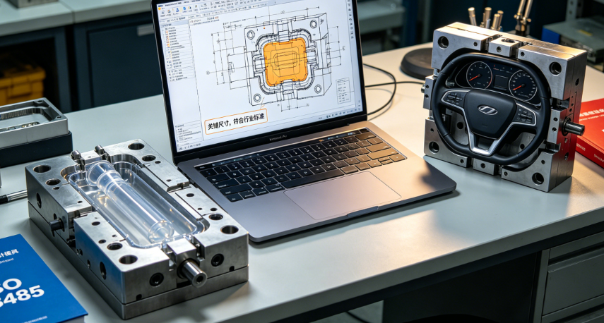
Automotive Injection Molds (EU/US OEM)
- H13 hardened steel standard for 1M+ shot runs
- Tight ±0.02–0.05mm tolerance for assembly mating parts
- Robust hydraulic side actions for complex interior/exterior trim undercuts
- Heat-resistant cooling systems for glass-filled PA66, PP+talc resins
- Full material traceability for automotive regulatory compliance
Medical Grade Disposable Molds (FDA, EU MDR Compliant)
- S136 stainless steel mandatory (anti-corrosion, easy medical sanitization)
- Mirror polish Ra ≤0.05μm for fluid contact surfaces to prevent residue buildup
- Separated cleanroom molding zones post-mold completion
- Minimal parting line flash, zero sharp edges for safe medical use
- Balanced multi-cavity layouts for high-volume disposable production (syringes, luer connectors, surgical housings)
Consumer Electronics Cosmetic Molds
- Class A surface finishing, hidden submarine gates
- Precise grain texturing matching brand aesthetic specs
- Low-stress cooling design to stop thin electronic housing warpage
- Anti-scratch cavity polishing for premium device exteriors
Industrial High-Temp Engineering Plastic Molds
- Conformal cooling inserts for PEEK, PEI, high-temperature polyimides
- Powder metallurgy steel for carbon-filled abrasive resins
- Reinforced mold base frames to handle high injection pressure
How To Calculate True Mold Cost
Many overseas suppliers quote low upfront tool prices then add hidden charges for DFM, simulation, trial runs, polishing or spare parts. At Zorapid, we deliver one fixed all-in quote covering:
- Full DFM engineering report
- Complete 3D mold design & Moldflow simulation
- Certified mold steel, heat treatment, CNC/EDM machining
- Polishing, texturing, mold assembly
- 3 rounds of T1-T3 trial molding + CMM inspection reports
- Standard spare wear parts (ejector pins, o-rings, slide inserts)
- Export packaging for sea/air shipping to US/EU ports
Key cost drivers you can adjust to fit your budget:
- Mold steel grade (P20 for low volume cuts upfront cost; S136/H13 for long production life)
- Cavity count (single cavity cheaper upfront, multi-cavity reduces per-piece mass production cost)
- Hot runner vs cold runner manifold
- Cosmetic finish class (mirror polish adds machining hours vs standard sand blast texture)
- Complex undercut slide/lifter mechanisms
We provide a transparent cost breakdown sheet with every quote so you see exactly where every dollar is allocated.
Zorapid’s One-Stop Complete Mold Design & Manufacturing Advantage For US/EU Clients
This handbook is built on our real-world experience serving Western OEMs—here’s what sets our full mold design & manufacturing service apart from generic tool shops:
- 20+ years export mold expertise, fully aligned with ISO 9001, ASME and EU MDR manufacturing standards
- In-house full vertical workflow: DFM → Moldflow → 3D Design → CNC/EDM Machining → Polishing → Mold Trials → Mass Molding
- Dedicated English-speaking project engineers assigned to every US/EU order, responsive 24-hour quote turnaround
- Full digital transparency: Weekly build progress photos/videos, complete simulation and inspection reports shared via cloud drive
- Precision tolerance capability down to ±0.005mm for high-end medical & semiconductor components
- Flexible lead times: Rapid bridge tooling 7–15 days; standard production molds 20–35 days (far faster than EU domestic tool shops with 60–120 day lead times)
- Long-term mold warranty + free lifetime technical design support for all molds we manufacture
- End-to-end service: After mold acceptance, we offer low-to-high volume injection molding, secondary finishing, assembly and direct shipping to your US/EU warehouse
We don’t just build molds—we act as your remote manufacturing engineering partner to resolve design, production and compliance challenges before they impact your product launch.
Quick Action Checklist To Launch Your Next Mold Project Smoothly
Save this checklist for your next RFQ to avoid delays and miscommunication with any mold supplier:
Share full 3D CAD STEP/IGS files + 2D engineering drawings with all tolerance specs
Define target annual production volume (sets steel grade & cavity layout)
List exact plastic resin grade, additives (glass fiber, flame retardant, medical grade)
Specify cosmetic class, surface finish, texture or polish requirements
Note all regional compliance rules (FDA, EU MDR, automotive OEM standards)
Confirm acceptable mold lead time and maximum budget
Request full DFM + Moldflow simulation report before steel cutting
Lock in T1-T3 trial acceptance criteria and FAIR documentation requirements
Closing Wrap-Up
Complete injection mold design and manufacturing isn’t just machining a steel cavity—it’s end-to-end engineering that ties your product design, material science, production efficiency and long-term profitability together. Every small choice in wall thickness, cooling layout, steel grade and venting ripples out to impact your entire product lifecycle.
This handbook gives you every critical framework to evaluate designs, avoid costly defects, and collaborate effectively with your tooling partner. If you’re a US or EU engineer or procurement manager ready to kick off your custom mold project.
Zorapid’s team is ready to deliver a free DFM review and transparent all-in quote within 24 hours. Drop your CAD files and project specs via our contact form, and we’ll map out a tailored mold design & manufacturing plan aligned with your timeline and quality standards.
FAQ
What mold steel should I pick for medical disposable parts sold in Europe?
S136 / STAVAX stainless steel is our standard recommendation. It’s corrosion-resistant for medical-grade resins, easy to sanitize, polishes to mirror Class A surfaces (Ra ≤0.05μm), and holds tight tolerances for 500k–1M production shots. It fully complies with EU MDR and FDA medical device requirements.
Cold runner vs hot runner – which one saves more money long-term?
Hot runners cut material waste and reduce cycle time by 20–35%, ideal for high-volume, expensive engineering plastics or transparent medical parts. Cold runners have lower initial mold cost and simpler maintenance, better for short-run prototypes. We compare both options in our handbook and quote both solutions for your reference.Cold runner vs hot runner – which one saves more money long-term?
Why do cheap molds always have burn marks and air bubbles on parts?
Most low-cost tool shops skip full parting line venting to save machining hours. Trapped air cannot escape during plastic filling, creating scorch marks, voids and dull surfaces. Zorapid’s standard vent design includes 0.01–0.03mm depth vents at every weld line, rib tip and flow end, meeting strict US/EU cosmetic acceptance rules.
What is Zorapid’s full mold production workflow?
DFM Review → Mold 3D Design + Moldflow Simulation → Steel CNC Rough Milling → Heat Treatment → Precision Semi-Finish Machining → Wire Sinker EDM → Polishing/Texturing → Full Mold Assembly → In-House T1-T3 Trials → CMM Dimensional Inspection → Final Mold Acceptance & Shipment. We send weekly photos/videos of all machining stages for full transparency.


