
Published:Zorapid.Ltd
If you design power connectors, sensor housings, PCB modules, EV wiring terminals, medical electronics or industrial control hardware, you’ve likely struggled with messy multi-step assembly.
Traditional manufacturing builds electronics piece-by-piece: machine metal contacts, mold separate plastic shells, then manually snap, glue or screw components together. This process creates three costly headaches:
- Loose tolerance stack-up between separate parts leading to poor electrical contact
- Slow, labor-heavy manual assembly that drives up mass production costs
- Weak adhesion between plastic and metal, causing separation under vibration or thermal cycling
Insert molding and overmolding solve all these pain points in one single injection shot. Hard metal terminals, PCBs, copper busbars, stainless steel pins and threaded inserts are locked permanently inside engineered plastic during molding. For complex multi-layer electronic components, this combined process delivers integrated, durable, space-saving assemblies impossible to replicate with separate part production.
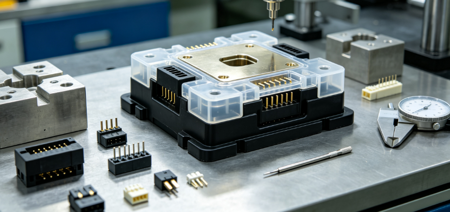
Core Definitions: Insert Molding vs Overmolding
Engineers often mix these two terms up, but they serve distinct roles for complex electronics:
Insert Molding
Solid pre-fabricated rigid inserts (brass terminals, stainless pins, threaded steel bushings, copper busbars) are manually or robotically placed into an empty mold cavity. Molten plastic injects around the inserts, permanently encapsulating them into a single unified component.
Best for: Embedded conductive contacts, threaded mounting inserts, metal grounding bars inside plastic housings.
Overmolding
A fully finished rigid plastic substrate (base housing, PCB carrier, hard plastic circuit frame) is placed into a secondary mold. A second softer or different-grade thermoplastic is injected over top to form grips, sealing gaskets, strain reliefs, insulation layers or ergonomic outer skins.
Best for: Dual-durometer connector grips, waterproof cable strain relief, shock-absorbent sensor casings, soft-touch user interfaces over rigid electronic frames.
Many complex electronic assemblies combine both processes: metal insert molding for internal conductive hardware, then secondary overmolding for outer sealing and ergonomics.
Unique Challenges of Overmolding Complex Electronic Hardware
Standard plastic injection molding only deals with molten plastic. Insert/overmolding adds rigid embedded components, creating manufacturing hurdles unique to electronics:
- Delamination & poor bonding between plastic and metal inserts Smooth un-treated metal surfaces create zero mechanical lock; thermal expansion mismatch pulls plastic away during temperature cycling.
- Micro flash shorting electrical circuits Tiny plastic flash seeping between metal terminal contacts causes electrical leakage, EMC failure or full short circuits in sensitive electronics.
- Thermal damage to delicate PCBs & thin brass micro terminals High melt temperature plastic can warp PCB traces, melt solder joints or bend thin conductive inserts if mold temperature is uncalibrated.
- Uneven shrinkage warping multi-material assemblies Metal and plastic have drastically different shrink rates; unbalanced wall thickness around inserts creates permanent bend after ejection.
- Complex multi-cavity mold alignment risk Multiple tiny inserts must be positioned with micron precision during mold loading; misalignment ruins pin positional tolerance for mating connectors.
- Strict EMC, insulation and cleanroom requirements Consumer, medical and semiconductor electronics demand zero conductive contamination and consistent dielectric thickness around embedded terminals.
6 Key Benefits of Insert & Overmolding for Electronic Assemblies
Eliminate Multi-Part Manual Assembly
All metal inserts and plastic housing form as one unified piece in a single molding cycle. Cut assembly labor costs by 40–70% vs separate molded + machined components. No screws, adhesive or snap fasteners required to hold contacts in place.
Superior Electrical Performance & Stable Contact Resistance
Inserts are fully encapsulated with consistent dielectric plastic thickness. No air gaps between metal and plastic that cause voltage breakdown, signal noise or fluctuating contact resistance for high-speed data/power electronics.
Vibration & Thermal Cycle Resistant Integration
When properly designed with undercut locking features on metal inserts, plastic grips tightly onto terminals. Assemblies withstand thousands of thermal cycles and industrial vibration without loose internal contacts — critical for EV, factory automation and medical devices.
Miniaturize Complex Electronic Packaging
Separate plastic shells and metal contact carriers waste valuable internal space. Overmolding embeds hardware directly within the housing walls, shrinking overall component footprint for compact wearables, miniature sensors and handheld test equipment.
Custom Dual-Material Functional Layers
Overmolding enables combining rigid structural plastic with soft TPE/TPU in one part: waterproof cable strain relief, anti-slip grips, shock absorption, and environmental sealing without secondary glue or gasket installation.
Improved EMI & Moisture Protection
Fully encapsulated metal grounding bars and sealed plastic layers block electromagnetic interference and prevent water/dust ingress into sensitive PCB and terminal zones, meeting IP54/IP67 ratings without extra sealing hardware.

Compatible Material Pairings for Electronics (Metal Inserts + Thermoplastics)
Bond strength is make-or-break for electronic overmolding. Below are Zorapid’s most validated material combinations for complex electronic components:
Common Metal Insert Materials
- C26000 Brass / Copper Terminals: Signal & power connector contacts, low electrical resistance
- 316L Stainless Steel Pins: Medical electronics, corrosion-resistant sensor probes
- Carbon Steel Threaded Inserts: Mounting hardware for PCB enclosures
- Copper Busbars: High-current EV power distribution modules
Primary Rigid Base Plastics (Insert Mold Core Housings)
- ABS / PC-ABS: Consumer electronics, low-cost control housings
- PC (Polycarbonate): High impact resistance, transparent sensor covers
- PA6 / PA66 Glass Filled: High-temperature automotive EV connectors
- PEEK / ULTEM: Medical & semiconductor high-temperature electronics, biocompatible insulation
Secondary Overmold Soft Materials (Seal, Grip, Strain Relief)
- TPE / TPU: Soft-touch grips, cable strain relief, waterproof sealing
- Silicone Overmold: Medical electronics, high-temperature liquid silicone rubber (LSR) for IP67 waterproof sensors
Critical Bonding Note
Smooth plain metal inserts will delaminate over time. We add micro knurls, undercuts, holes or chemical surface etching on all metal inserts to create mechanical interlocks that lock plastic permanently to metal substrates.
Zorapid’s Full In-House Insert & Overmolding Workflow for Complex Electronics
We own every stage of production from DFM mold design to electrical testing, no outsourced insert machining or third-party molding vendors that risk circuit contamination and delayed lead times.
Electronics-Focused DFM Analysis
Our mold engineers run a dedicated overmolding DFM check before cutting any mold steel, targeting electronic-specific risks:
- Verify metal insert undercut/knurl geometry for strong plastic-metal bonding
- Balance wall thickness around embedded terminals to eliminate uneven shrinkage warpage
- Optimize gate placement away from delicate PCB and thin micro brass terminals to avoid melt erosion
- Calculate thermal expansion offsets between metal and plastic to preserve pin positional tolerances post-mold cooling
- Size vents to eliminate flash risk between adjacent conductive contacts (prevents electrical shorting)
- Reserve clearance for post-mold electrical test probes and assembly mating surfaces
We deliver annotated CAD revisions, bonding improvement suggestions and full lead time breakdowns within 24 hours for all electronic NPI projects.
Pre-Mold Insert Prepping & Fixture Design
- Precision machining of all metal terminals, pins and busbars in our sheet metal/Swiss turning division
- Surface texturing (knurling, etching) applied to insert contact zones for mechanical interlock
- Custom loading fixtures manufactured to position multiple micro inserts with ±0.003mm alignment accuracy
- Batch pre-cleaning to remove oil, oxidation and micro metal particles that cause mold defects and electronic contamination
Precision Injection Molding for Multi-Component Assemblies
- Manual or robotic precision loading of inserts/PCB substrates into temperature-controlled mold cavities
- Calibrated low-shear injection parameters to avoid high melt heat damaging solder joints and thin brass shafts
- Controlled slow fill speeds to eliminate flash between closely spaced conductive terminals
- Dual-shot mold capability for integrated insert molding + secondary TPE overmold in one mold tool
- Extended cooling cycles to balance plastic/metal shrinkage and reduce post-ejection warpage
Post-Mold Deburr, Surface Finishing & Electrical Testing
- Micro ultrasonic deburring removes tiny plastic flash without scratching metal contact surfaces
- Optional finishing: laser engraving part numbers, matte/textured mold finishes, UV hard coating for electronic housings
- In-house electrical continuity testing to screen for short circuits caused by flash bridging terminals
- Full solvent cleaning to eliminate molding residue that causes EMC interference or outgassing in cleanroom environments
Full QA Inspection for EMC, Fit & Dimensional Compliance
Every batch of complex overmolded electronics undergoes multi-layer inspection:
- Optical vision measurement to verify terminal positional tolerance and dielectric wall thickness
- Hi-pot dielectric strength testing to validate insulation performance
- Vibration cycle testing for automotive/industrial electronic durability validation
- Full mold inspection reports, material COAs and electrical test logs packaged with shipments for OEM audit trails
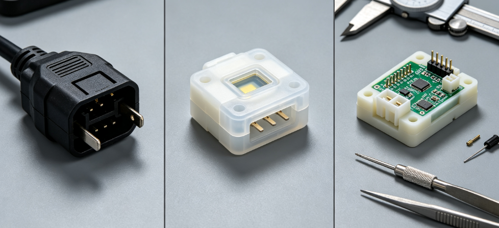
Common Complex Electronic Parts Built With Insert / Overmolding
These are the highest-demand overmolded electronic assemblies our OEM and Tier 1 clients produce at Zorapid:
- Automotive & EV Electronics
- High-current overmolded busbar power connectors
- Waterproof sensor housings with embedded brass signal pins
- Battery module terminal blocks with integrated threaded mounting inserts
- Medical Electronic Hardware
- Disposable probe assemblies with stainless steel micro pin inserts
- LSR silicone overmolded patient monitoring cable strain reliefs
- Biocompatible PEEK insert molded implant sensor carriers
- Industrial & Semiconductor Electronics
- Cleanroom PCB vacuum fixture terminal blocks
- EMI-shielded control module housings with embedded copper grounding bars
- Multi-pin test socket connectors with micro brass insert terminals
- Consumer & Handheld Hardware
- Dual-shot charging cable connectors with strain relief overmold
- Miniature sensor enclosures with internal threaded steel inserts
- Ergonomic device grips over rigid PCBA substrates
Critical DFM Design Rules To Avoid Delamination, Flash & Warpage
Apply these rules during CAD design to cut scrap rate and eliminate costly mold rework for complex electronic overmolds:
- Add mechanical interlocks on all metal inserts: knurls, through-holes, peripheral undercuts (no smooth bare metal contact surfaces)
- Maintain uniform plastic wall thickness (1.2–2.5mm) surrounding all embedded terminals; avoid heavy plastic mass concentrated on one side of inserts
- Separate adjacent conductive pins with minimum 0.8mm plastic barrier thickness to stop flash shorting
- Locate injection gates far away from thin brass micro terminals and solder PCB zones to prevent melt heat damage
- Keep insert positional datum surfaces fully exposed outside plastic overmold for post-mold alignment testing
- Limit sharp 90° corners around embedded inserts; add minimum 0.5mm radii to reduce shrinkage stress and delamination
- For dual-shot overmolding: Ensure rigid substrate fully cools before secondary soft TPE injection to prevent melting deformation
Real Client Case: Overmolded PCB Connector Housing with Brass Terminal Inserts
A US industrial sensor OEM needed complex overmolded connector assemblies for factory automation equipment, combining insert molded brass signal terminals and secondary TPE cable strain relief overmold.
Original Design & Supplier Pain Points
- Smooth untextured brass inserts suffered consistent plastic delamination under thermal cycling testing
- Poor vent design created micro flash bridging adjacent pins, triggering 30% electrical short scrap rate
- Separate vendors machined terminals, built molds and performed electrical testing, extending lead time to 22 days
- Uneven wall thickness around terminals caused severe housing warpage, failing mating connector fit tests
Zorapid Insert & Overmolding Solution
- DFM redesign added micro knurl interlocks on all brass insert surfaces to eliminate delamination
- Resized mold vent depths to 0.015mm and repositioned gates to eliminate flash between contact pins
- Balanced plastic wall thickness around terminal zones to equalize shrinkage and stop warpage
- Full in-house workflow: Swiss turning brass terminals → mold fabrication → dual-shot insert + overmold molding → electrical continuity testing
- 100% batch hi-pot dielectric testing to screen all potential short circuits before shipment
Final Outcome
Scrap rate dropped from 30% to under 1.2%, all thermal cycle and vibration validation tests passed first submission. Total project lead time cut from 22 days to 9 days, and the OEM now outsources all complex overmolded electronic connectors exclusively to Zorapid.
Insert & Overmolding Batch Cost & Lead Time Breakdown
All timelines calculated from DFM CAD approval to finished, tested parts (excluding international shipping):
Low-Volume NPI Prototypes (1–50 units, prototype mold)
- Tooling lead time: 7–10 business days
- Molding + testing production: 3–5 days
- Cost driver: Prototype mold setup fees dominate small-batch pricing
- Best for: Lab validation, pre-production electrical testing
Mid-Volume Pilot Batches (50–500 units, single-cavity production mold)
- Tooling lead time: 12–18 business days
- Production turnaround: 4–7 days per batch
- Cost balance: Upfront mold cost amortizes across moderate quantities
Mass Production (1,000+ units, multi-cavity dual-shot mold)
- Tooling lead time: 18–28 business days
- Repeat batch turnaround: 3–6 days
- Cost advantage: Ultra-low per-unit cost with fully automated insert loading and molding cycles
Most Frequent Overmolding Defects + Quick Fixes
- Delamination between plastic and metal inserts Fix: Add knurl/through-hole interlocks; optimize insert surface etching in pre-mold prep
- Micro flash bridging electrical terminals (short circuits) Fix: Reduce injection pressure; shrink vent depth; reposition gates away from pin gaps
- Warped housing after ejection Fix: Balance wall thickness around inserts; extend cooling cycle; adjust mold temperature balance
- Burnt/damaged PCB solder joints Fix: Lower melt temperature; slow injection fill speed; isolate PCB from direct gate flow
- Poor adhesion between rigid base and TPE overmold layer Fix: Add texture to rigid substrate overmold zones; use compatible matched resin grades
FAQ
Can insert overmolding fully encapsulate populated PCBs with soldered components?
Yes. We use low-shear, low-temperature calibrated molding parameters and custom protective fixture shielding to avoid damaging solder joints and surface-mount components during injection.
What minimum size brass micro terminal inserts can you overmold for miniature electronics?
We support Swiss turned brass inserts starting at 0.3mm diameter, with precision mold loading fixtures to maintain alignment during multi-shot overmolding.
Is LSR silicone overmolding available for medical waterproof electronic assemblies?
We offer in-house liquid silicone dual-shot overmolding for medical-grade IP67 sealed sensors and patient monitoring hardware, compliant with biocompatibility standards.
Do you provide full electrical test documentation for OEM EMC and safety audits?
Every shipment includes continuity test logs, hi-pot insulation reports, material COAs and dimensional inspection data required for industrial, medical and automotive electronic compliance audits.
Can I transition from prototype single-cavity molds to mass multi-cavity overmold tools without redesigning inserts?
Absolutely. Our DFM standardizes insert geometry to be fully compatible across prototype and production mold platforms, eliminating rework and re-qualification costs when scaling batches.
Wrap-Up
Complex electronic assemblies with embedded metal contacts, PCBs and dual-material sealing layers cannot be efficiently manufactured with separate machining and single-shot molding. Insert and overmolding integrates all critical hardware into one durable, space-saving component while cutting assembly labor and improving electrical reliability.
The biggest manufacturing risks — delamination, terminal shorting, PCB thermal damage and warpage — all stem from incomplete DFM analysis and fragmented outsourced production workflows. Zorapid’s full-service model combines in-house insert precision machining, dedicated electronic overmold mold design, dual-shot injection molding, electrical functional testing and full compliance QA under one roof.
Whether you need small NPI prototype batches of sensor connectors or millions of mass-production EV power modules, our electronics-focused mold engineering team eliminates scrap, reduces lead times and delivers consistent, test-ready overmolded electronic components aligned with your product launch schedule.
Request Your Free Electronic Overmold DFM Review & Transparent Quote
Send your assembly CAD files, metal insert specs, plastic material pairings, batch volume and electrical compliance requirements. Our overmold engineering team will flag delamination, flash and warpage risks, share optimized CAD revisions, and provide itemized pricing for prototype and mass production mold + molding services.


