
Published:Zorapid.Ltd
High-volume CNC turning (shafts, pins, bushings, automotive valve cores, fastener blanks) relies on consistent short cycle times to hit daily output targets. Most generic CAM-generated turning programs carry avoidable waste: redundant cutting passes, slow feed rates, excessive retracts, unbalanced chip load and inefficient grooving sequences.
Every 1–3 second cycle cut on a mass run of 100,000+ parts adds up to thousands of extra production hours, lower labor overhead, less spindle wear and higher daily throughput. Toolpath optimization does not require new machine hardware — it only adjusts CAM motion logic, cutting sequence and idle travel paths to maximize metal removal rate (MRR) while keeping inserts within safe wear limits.
This guide delivers shop-proven toolpath adjustments for all common turning operations: longitudinal roughing, facing, grooving, parting and threading, tailored to continuous bar-feed mass production lathes. All strategies balance faster cycles with stable tool life, critical for unmanned overnight mass runs.
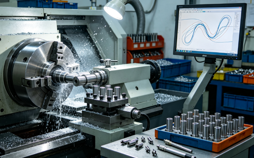
Core Cycle Time Loss Points in Standard Turning Programs
Before adjusting toolpaths, identify these four major time sinks present in default CAM turning outputs:
- Conservative constant-depth roughing with tiny stepdowns, requiring dozens of redundant passes
- Full retract to safe Z/X clearance after every cut segment, creating long idle rapid moves
- Equal stock allowance across all features; extra finishing passes on low-tolerance non-critical surfaces
- Sequential single-point grooving, instead of multi-pass plunge or wide insert split grooving
- Slow threading retract routines and unnecessary dwell pauses at thread start/end
- Unoptimized entry/exit angles causing unstable chip load, forcing reduced feed speeds across the whole program
Rough Turning Toolpath Optimization
Roughing accounts for 60–80% of total part cycle time; optimized rough toolpaths deliver the largest throughput gains.
Trochoidal Oscillating Roughing Paths
Replace fixed straight longitudinal stepdowns with trochoidal turning paths.
- Oscillating radial motion keeps consistent chip thickness even at deep cuts
- Eliminates peak overloads on inserts, allowing 20–40% higher feed rates
- Reduces total rough pass count by merging multiple shallow cuts into fewer high-MRR passes
- Best for tough alloys: titanium, Inconel, hardened steel, high-strength automotive aluminum
Variable Step-Depth Roughing (Adaptive Stock Removal)
Standard CAM uses uniform depth per pass regardless of blank stock shape. Adaptive variable stepdown adjusts cut depth automatically:
- Deep stepdown on large stock areas
- Shallow stepdown only near shoulders, fillets and tight radii
- Cuts total rough travel distance by 25–35% on contoured shafts and stepped pins
Reduce Safe Retract Distances (Conditional Minimal Retracts)
Default CAM retracts fully to machine safe X/Z after every cut segment. Optimized logic:
- Only minimal X retract (0.1–0.3 mm clear stock) between continuous rough passes on the same outer diameter
- Full safe retract only when switching major feature groups (OD → shoulder → bore)
- Eliminates hundreds of long rapid idle moves per part in mass batches
Combine Facing & OD Roughing in One Tool
Avoid separate dedicated facing tool offsets; program the OD rough insert to front-face the blank tip before longitudinal turning. Removes one full tool change and idle turret travel time per piece.
Finishing Toolpath Tweaks to Cut Secondary Passes
Finishing is often overlooked for optimization, but redundant light passes add cumulative cycle waste over millions of parts.
- Segmented stock allowance assignment
- Thin 0.08–0.12 mm finish stock on tight GD&T datum surfaces
- Larger 0.2–0.3 mm stock on non-critical cosmetic OD/ID surfaces
- Fewer light finishing passes on low-precision features
- Single continuous contour finishing path Program one uninterrupted finish pass instead of splitting contour into separate shoulder, radius and straight segments; removes micro rapid retracts between segments.
- Optimize lead-in / lead-out angles Use 15–30° angled entry instead of straight perpendicular plunge to eliminate feed slowdown at cut start; avoids built-up edge that forces reduced surface feeds.
- Eliminate unnecessary dwells Remove default CAM dwell pauses at every radius and corner; only add dwell if surface roughness spec strictly requires it.
Grooving & Parting Toolpath Optimizations for Bar Feed Mass Runs
Grooving and parting are frequent bottlenecks on bar-fed high-volume turning lines due to slow single-plunge paths.
5.1 Wide Insert Split Grooving Toolpaths
For wide grooves (≥3 mm width):
- Use a wider grooving insert and program overlapping stepped plunge paths instead of multiple narrow single plunges
- Cuts total grooving travel distance by 40–60% vs sequential narrow plunges
Peck Grooving with High Rapid Retract Mini-Strokes
Short 0.2–0.5 mm chip-breaking retracts instead of full X retract after each plunge depth:
- Chips break consistently, no feed rate reduction for chip evacuation
- Minimal idle travel between peck strokes vs full stock clearance retracts
Optimized Parting Off Toolpaths
- Ramp-down parting path instead of straight flat plunge to balance chip load
- Gradually increase feed as cut depth progresses to shorten final severing time
- Minimal X retract after parting, immediate rapid return to blank stock for next piece
Multi-Groove Linking
Machine all identical grooves on one shaft in a single continuous toolpath without full turret retracts between each groove position.
Thread Turning Efficient Toolpath Strategies
Standard single-pass thread cycles waste massive time on long thread runs for bolts, connector pins and hydraulic fittings.
- Variable infeed thread roughing (trapezoidal stepped depth) Gradually increase radial cut depth on early passes, reduce depth on finishing thread passes; fewer total passes vs equal-depth uniform threading.
- Alternating flank infeed instead of full radial plunge Distributes wear evenly across both insert thread flanks, allows higher feed speed without chipping inserts.
- Shortened thread entry/exit overtravel Trim default CAM 2–3 thread pitch overtravel to 0.5–1 pitch; removes idle slow feed travel at thread start and end.
- Skip redundant finish thread passes for non-critical class 2A threads Only keep one light finish pass for mass hardware with loose thread tolerance specs.
Non-Cutting Idle Motion Elimination
Idle rapid moves, tool changes and turret rotation add 2–8 seconds per part, which multiplies drastically over mass batches. Optimize toolpath motion logic to cut dead time:
- Turret tool order re-sequencing Group all OD tools together, all grooving tools together, all bore tools together; minimize turret rotation angle between consecutive operations.
- Conditional rapid clearance limits Lock minimal X/Z clearance offsets for same-feature continuous cutting; only full safe retract when switching part families or bore/OD operations.
- Merge multiple small facing/chamfer operations into one toolpath Avoid separate turret calls for tiny chamfers or edge breaks; integrate into rough or finish contour paths.
- Eliminate redundant spindle stop/start cycles Keep spindle running at consistent speed between linked cutting operations; only stop spindle for part ejection or bar feed advance.
Toolpath Strategies to Extend Tool Life & Reduce Unplanned Stops
Cycle time optimization fails if faster cutting causes frequent insert changes and line downtime. These toolpath rules balance speed and tool longevity for unmanned mass production:
- Maintain constant chip load via trochoidal and adaptive roughing Avoid sudden deep single plunges that spike cutting force and crack inserts.
- Smooth radius blending on all entry/exit cut paths Sharp 90° entry angles create impact shock; angled leads reduce edge chipping and allow sustained high feeds.
- Avoid full tool engagement on narrow thin ribs Program staged stepped cuts to split material removal, prevent insert overload and thermal hotspots.
- Program consistent coolant flood aligned with cutting path entry Toolpath sync coolant activation only at cut start, turn off during idle rapid moves to reduce pump wear without sacrificing tool cooling.
Machine Parameter Matching Optimized Toolpaths
Toolpath gains are lost if spindle speed, feed and lathe motion parameters are not aligned to revised CAM paths:
- Raise rapid traverse G00 speed limits after minimizing retract distances
- Increase cutting feed rates matched to stable trochoidal chip load paths
- Optimize look-ahead block processing (G05/G08) for smooth high-speed contour finishing
- Reduce acceleration/deceleration jerk values for short segmented grooving paths to avoid feed slowdowns
- Activate lathe bar feed synchronous motion linking part ejection and next cut toolpath
Real Client Mass Production Case: Automotive Shaft Turning Cycle Reduction
A Tier 1 automotive supplier ran 120,000 annual output of steel transmission shafts on bar-fed twin-spindle lathes. Original standard CAM turning programs had 42-second total cycle time per shaft.
Original Toolpath Waste Points
- Uniform shallow rough stepdowns with full retracts after every cut segment
- Separate dedicated facing tool creating extra turret change time
- Slow equal-depth single-plunge grooving for dual oil seal grooves
- Long full retract idle moves between OD rough and finish contour
Zorapid Toolpath Optimization Adjustments
- Switched roughing to adaptive trochoidal variable stepdown paths, minimal conditional retracts
- Integrated front facing into OD rough toolpath, eliminated one tool change
- Wide insert split grooving linked for both seal grooves, peck mini-retract chip breaking
- Reordered turret tool sequence to cut rotation travel distance
Final Outcome
Total cycle time reduced from 42s to 27s per shaft (35.7% cycle cut). Daily machine output rose from 1,700 parts to 2,640 parts, insert service life extended 22% with no increase in scrap rate.
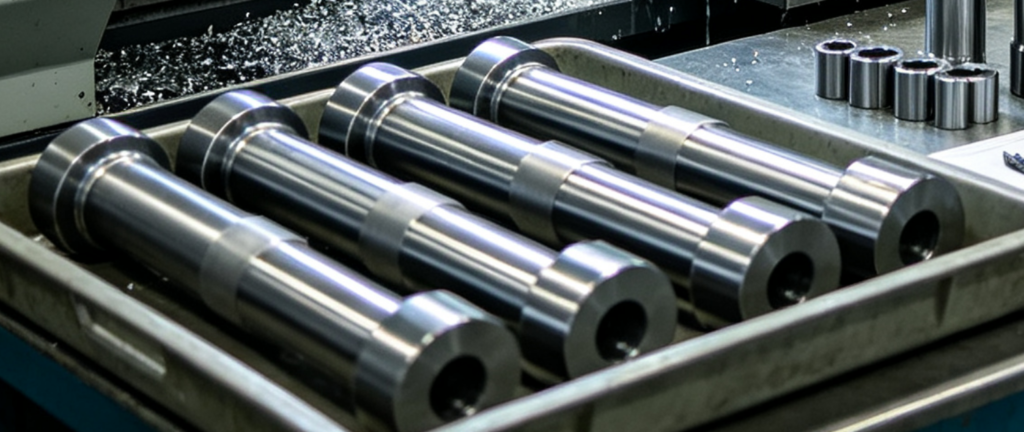
Toolpath Optimization Checklist Before Mass Production Launch
Run this CAM simulation checklist to lock optimized turning programs for high-volume batches:
- Roughing set to adaptive trochoidal variable stepdown cutting
- Minimal conditional retracts enabled, full safe retracts only for feature switches
- Facing merged into OD rough toolpath to eliminate separate tool station
- Grooving paths use wide insert overlapping plunge or short peck mini-retracts
- Threading uses alternating flank infeed with reduced entry/exit overtravel
- Turret tool sequence reordered to minimize rotation angle between consecutive cuts
- Segmented variable finish stock allowance assigned per feature tolerance
- All sharp cut entry angles replaced with 15–30° smooth lead-in paths
- Unnecessary dwell pauses removed from radii and contour corners
- CAM simulation run to verify no idle rapid travel bottlenecks or collision risks
- Short trial batch run to validate insert wear stability at optimized feed/speed
Common Toolpath Mistakes That Inflate Turning Cycle Times
- Mistake: Uniform shallow fixed rough stepdown across the entire blank Fix: Switch to adaptive variable depth trochoidal roughing to cut total pass count
- Mistake: Full X/Z safe retract after every single cutting pass Fix: Enable conditional minimal stock clearance retracts for continuous same-feature cutting
- Mistake: Separate dedicated tool for small chamfers, edge breaks and facing Fix: Integrate minor edge operations into primary rough/finish toolpaths
- Mistake: Sequential single narrow plunges for wide grooves Fix: Deploy wide grooving insert with overlapping stepped plunge paths
- Mistake: Long default thread overtravel and equal-depth threading passes Fix: Alternating flank variable infeed + trimmed entry/exit overtravel
- Mistake: Random turret tool order forcing large rotation moves between operations Fix: Group OD, grooving, bore tools sequentially to limit turret rotation travel
FAQ
How much cycle time reduction can toolpath optimization deliver on mass turning runs?
Typical stable gains range from 25–40% total cycle reduction for standard shaft, pin and bushing mass parts, with no capital machine upgrades required.
Does faster optimized toolpath cutting shorten insert service life?
Proper trochoidal constant chip load paths evenly distribute cutting force and heat, often extending insert life by 15–25% vs erratic standard fixed-step roughing paths.
Can optimized turning toolpaths be reused across identical part repeat batches?
Yes. Lock finalized CAM parameters and toolpath logic into a master template for recurring mass production SKUs to avoid rework on new order setups.
Are trochoidal turning paths suitable for hard-to-machine alloys like Ti6Al4V or Inconel?
Trochoidal roughing is highly recommended for high-strength alloys; consistent low peak chip load eliminates insert chipping and allows significantly higher feed rates.
What is the fastest way to eliminate idle turret/rapid move waste?
Re-sequence turret tool order to group all related cutting operations together and enable conditional limited retract logic in CAM post-processor settings.
Wrap-Up
Shortening mass production turning cycles does not rely on faster spindle speeds alone — structured toolpath optimization removes built-in idle travel, redundant cutting passes and unstable chip load limits from generic CAM default programs.
The highest throughput gains come from reworking roughing paths via adaptive trochoidal variable stepdown cutting, paired with minimal conditional retracts and merged secondary edge operations. Grooving, parting and threading toolpath tweaks deliver secondary consistent time savings, while reordering turret tool sequences eliminates hidden idle turret rotation waste.
When paired with matched machine motion parameters and chip-stable entry/exit geometry, optimized toolpaths simultaneously raise daily output and extend insert service life, critical for unmanned continuous bar-feed mass turning lines.
Zorapid’s process engineering team audits all turning CAM programs for mass production batches, applying this full toolpath optimization workflow before full production launch to cut cycle times, lower consumable costs and boost line throughput for automotive, aerospace and industrial turned components.
Request Free Turning Toolpath Cycle Time Audit
Share your part CAD, current CAM turning program and target daily batch volume. Our process engineers will simulate revised optimized toolpaths, quantify projected cycle time reduction and deliver a finalized production-ready CNC program template.


