
Published:Zorapid.Ltd
Complex mold surfaces include deep steep cavities, freeform optical contours, undercut parting lines, curved ribs and conformal cooling channels. Traditional 3/4-axis machining requires 3–6 separate re-clamping steps to machine all mold faces, creating unavoidable cumulative positioning error, visible tool step lines and heavy manual polishing workloads.
Single-clamp simultaneous 5-axis machining locks the mold blank into one zero-point fixture for the entire production sequence: roughing, semi-finish, finish, corner rest machining and all angled cooling hole drilling. The machine’s rotating B/C axes tilt the spindle to access every mold surface with short, rigid cutting tools, eliminating long overhang tool chatter and broken surface continuity across split setups.
This guide focuses on mold steel (S136, Stavax, H13, P20) single-setup workflows, delivering consistent mirror-ready freeform surfaces, shorter total lead times and zero alignment mismatch between cavity, core and parting lines.
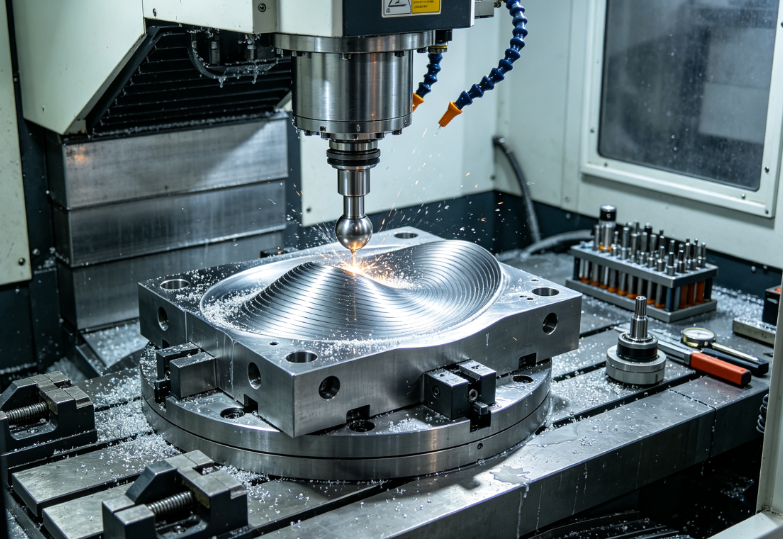
Core Defects of Multi-Setup 3/4-Axis Mold Machining
All these quality and efficiency issues disappear with single-clamp 5-axis processing:
- Cumulative positioning tolerance drift across multiple re-clamps → parting line mismatch, uneven mold wall thickness
- Long slim extended ball nose tools for deep cavities → severe chatter ripples, poor surface Ra, frequent tool breakage
- Visible step lines between different setup machining zones → 2–5x extra manual polishing hours
- Extra operator time for re-indicating, re-probing and fixture changeovers → long mold delivery lead times
- Uneven stock allowance across curved surfaces → inconsistent finishing depth, localized over-cutting
- Impossible collision-free access to steep undercut contours → manual EDM electrode sinking required
6 Key Production Advantages of Single-Clamp 5-Axis Mold Machining
Eliminates Multi-Setup Cumulative Position Error
All mold geometry shares one unified workpiece zero point. Cavity contours, parting surfaces and cooling holes maintain perfect positional consistency; no mold mismatch or flash risk after assembly. GD&T contour accuracy stabilizes ±0.003–0.008 mm across the entire mold block.
Short Rigid Tools Remove Chatter & Boost Surface Quality
5-axis spindle tilting orients the blank so short, stubby ball nose and barrel cutters reach deep mold cavities. Tool overhang length reduced by 50–70% vs 3-axis long tools, cutting vibration by 75% and enabling mirror-ready Ra ≤0.2 μm as-machined surfaces. Manual polishing labor drops by 60%+.
Continuous Uninterrupted Freeform Finishing (No Step Lines)
Simultaneous 5-axis surface projection toolpaths machine the entire mold curved profile in one continuous pass, eliminating setup boundary tool marks that require extensive hand polishing. Critical optical molds (automotive lenses, medical cassettes) meet cosmetic specs without secondary EDM.
All Operations Completed In One Fixture
Roughing, semi-finish, freeform finishing, corner rest machining, angled cooling channel drilling and parting line trimming run sequentially without unclamping. Cuts total mold cycle time by 30–50% vs multi-setup 3-axis workflows.
Access Undercuts & Steep Walls Without EDM Sinking
Tilted spindle angles reach negative draft undercuts, deep narrow ribs and steep cavity walls collision-free, reducing electrode design and sink EDM outsourcing costs for complex mold geometry.
Stable Uniform Stock Allowance Across All Curved Surfaces
CAM 5-axis simulation calculates consistent semi-finish stock (0.1–0.15 mm) over variable-depth mold contours, eliminating localized heavy finishing cuts that cause tool deflection and uneven surface texture.
Single-Clamp Mold Fixturing Design Rules
Fixture rigidity and full collision clearance are the foundation of stable single-setup mold machining:
- Zero-point modular fixture base (industry standard for mold blocks)
- Standardized pull-stud positioning repeatability ±0.002 mm for rework or secondary batch runs
- Open-frame fixture design leaves full mold cavity sides exposed for 5-axis spindle tilt access
- Avoid full solid base plates that block low-angle B-axis rotation
- Custom machined aluminum nest for contoured mold blanks
- Nest matches raw blank outer profile to distribute clamping force evenly; no localized mold steel deformation
- Clamp only on raw stock surplus material zones, never near finished mold cavity surfaces
- Clamping height clearance rule
- Leave minimum 10–15 mm vertical gap between fixture jaws and lowest mold cavity feature to avoid spindle collision at maximum tilt angles
- Sacrificial stock tabs for large thin mold inserts
- Integrate temporary connecting tabs on mold blank edges to avoid unsupported free-standing thin core ribs during heavy roughing; tabs trimmed in final finish pass
- Vacuum chuck for flat thin mold inserts
- Full surface vacuum adsorption eliminates jaw clamp denting on polished mold steel parting surfaces; ideal for small medical disposable mold inserts
Tool Selection & Holder Standards for Complex Mold Single-Setup Runs
Maximize rigidity and collision avoidance for one-clamp full mold processing:
- Shortest feasible solid carbide ball nose / barrel finishing cutters
- Barrel (tapered swarf) cutters preferred for large freeform mold surfaces: wider contact radius reduces stepover count and cycle time.
- Limit tool overhang to ≤1.5× tool diameter for all finishing operations
- Shrink-fit tool holders (mandatory vs ER collets)
- 30–40% higher gripping rigidity, minimal runout (<0.001 mm) for mirror mold finishing
- Collision-optimized slim neck tool bodies
- Narrow tapered tool necks prevent spindle housing collision during steep B-axis tilting into deep mold cavities
- Graded tool set for single-clamp sequential machining
- Large diameter bull nose for roughing → medium ball nose semi-finish → small radius ball nose for corner rest machining → barrel swarf cutter for main freeform finish
- Coatings: TiSiN high-temperature coating for hard mold steel (S136, H13) to extend tool life under continuous single-setup long cycles
Optimized 5-Axis Toolpath Strategies for Smooth Mold Freeform Surfaces
All toolpaths are programmed for single-clamp continuous execution, with full collision simulation before machine run:
5-Axis Trochoidal Roughing for Deep Mold Cavities
- Constant chip-load oscillating roughing path avoids heavy single-pass radial cuts that deflect thin mold core ribs
- Spindle tilted slightly away from steep cavity walls to use short rigid tools, eliminate long overhang chatter
- Adaptive variable stepdown reduces total rough travel distance by 25–35% vs fixed-depth 3-axis roughing
- Uniform 0.12–0.18 mm semi-finish stock left across all freeform contours
Constant-Tilt Simultaneous Finishing (Surface Projection / Swarf Milling)
Two core finishing strategies for mold freeforms:
- Surface Projection Finishing (General Curved Cavities) Tool axis maintains consistent 10–15° tilt off surface normal, ball nose tip stays centered on mold surface, evenly distributed cutting load for uniform Ra finish. Continuous single-pass contour across entire mold without retracts between curved zones.
- Swarf Line Finishing (Large Smooth Freeform Optical Molds) Barrel cutter flank sweeps along mold curvature; wider contact area reduces stepover spacing, slashes finishing cycle time while eliminating micro cusp height that requires polishing. Ideal for automotive lamp, cosmetic container mold surfaces.
- Key rule: Avoid vertical straight-down tool orientation on steep walls; tilt spindle to prevent tool tip scrubbing and surface wave marks.
5-Axis Rest Machining & Clearance Corner Clean-Up
- Automatic residual stock detection from rough/semi-finish passes; small radius ball nose tools tilted to reach deep mold fillets and rib intersections without fixture re-clamp
- Controlled minimal retracts only between separate mold feature groups; eliminate full safe Z/X retracts after every corner pass to cut idle rapid travel time
Machine Parameter Tuning for Single-Clamp Mold Steel Machining
Stable long single-setup runs require balanced speed, feed and coolant to avoid thermal distortion and tool wear:
- Spindle speed range
- Roughing H13/S136 mold steel: 8,000–12,000 RPM
- Mirror finishing freeform surfaces: 15,000–20,000 RPM low-vibration high-speed spindle
- Feed per tooth (fz) calibrated for short rigid tools
- Roughing: fz 0.08–0.15 mm/tooth
- Finishing swarf/surface projection: fz 0.04–0.08 mm/tooth for ultra-smooth mold Ra
- RTCP Tool Center Point Control permanently enabled Compensates B/C axis rotation to lock tool tip precisely on programmed mold surface path, eliminates positional drift during simultaneous tilting motion.
- Full flood high-pressure coolant aligned to cutting contact point Continuous heat removal prevents mold steel thermal expansion distortion during multi-hour single-clamp machining cycles.
- Machine thermal compensation active Real-time spindle and axis temperature offset correction to maintain micron contour accuracy over long unattended single-setup runs.
Full Single-Clamp Mold Machining Standard Workflow
Complete sequence executed without unclamping the mold blank:
- Pre-machining CAM full collision simulation (blank + fixture + spindle housing + tool holder)
- Zero-point fixture mounting, single coordinate zero set via machine probe
- 5-axis trochoidal roughing of full cavity, core and parting line stock removal
- 5-axis semi-finish simultaneous tilting pass, uniform residual stock left on all freeforms
- 5-axis rest machining for tight fillets, rib corners and deep cavity residual stock
- Continuous simultaneous 5-axis surface projection/swarf finishing for all mold freeform surfaces
- 5-axis tilted spindle drilling of all angled conformal cooling channels and ejector pin holes
- Final light trimming pass on parting line and mold outer datum edges
- In-machine CMM probing of critical mold contour GD&T without fixture removal
- Unclamp finished mold block for heat treatment / polishing
Real Client Case: Automotive Lamp Freeform Mold Single-Setup Optimization
A Tier 1 automotive mold maker produced PC headlamp lens freeform mold inserts (S136 stainless steel, optical mirror finish requirement). Original process used 4 separate 3-axis setups with 42-hour total machining time.
Original Multi-Setup Pain Points
- Visible setup boundary step lines across optical freeform surfaces, requiring 18 hours of manual polishing per mold
- Long 160 mm overhang ball nose tools caused heavy chatter, Ra only reached 1.6 μm after machining
- Mismatched parting line contour from re-clamp positioning error, mold flash during trial runs
- Separate fixture setup for angled cooling holes added 8 hours extra labor time
Single-Clamp 5-Axis Implemented Solutions
- Zero-point open-frame fixture with full B-axis tilt clearance, one unified workpiece zero
- Short shrink-fit barrel swarf cutters, tool overhang reduced to 35 mm max
- Continuous simultaneous 5-axis swarf finishing path across entire optical lens contour
- All rough, semi-finish, rest machining and cooling hole drilling completed in single clamp
Final Outcome
Total machining time cut from 42h to 19h, manual polishing labor reduced from 18h to 4h, parting line contour mismatch eliminated, as-machined surface Ra stabilized ≤0.2 μm meeting optical mold specs.
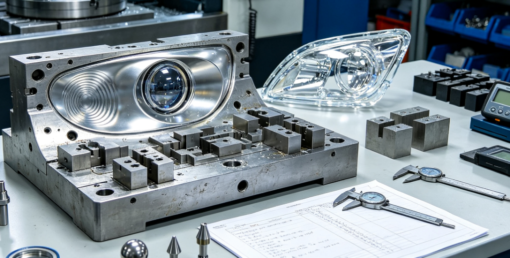
Common Single-Clamp 5-Axis Mold Machining Defects & Fixes
- Chatter vibration ripples on deep curved mold walls Root cause: Excessive tool overhang, ER collet holder low rigidity Fix: Switch to shrink-fit short tools, tilt spindle to minimize extension length, lower radial roughing stepdown
- Uneven surface finish across freeform mold surfaces Root cause: Fixed vertical tool orientation on steep walls, inconsistent chip load Fix: Enable constant 10–15° surface tilt simultaneous finishing, use swarf barrel cutters
- Spindle collision during B-axis maximum tilt Root cause: Insufficient fixture clearance, unvalidated CAM simulation Fix: Widen fixture jaw gap, run full machine collision dry run before production cut
- Contour positional drift across long single-setup runs Root cause: Disabled RTCP, uncompensated spindle thermal growth Fix: Activate RTCP and machine thermal compensation, periodic in-machine probe offset check
- Residual stock left in deep mold fillet corners Root cause: No dedicated 5-axis rest machining toolpath Fix: Add automatic residual stock detection rest pass with small radius tilted ball nose tool
Pre-Production CAM Simulation Checklist for Single-Clamp Mold Jobs
Validate all items before loading mold blank onto 5-axis machine:
- Full collision simulation including mold blank, fixture, spindle head, tool holder and cutting tool
- RTCP function enabled for all simultaneous 5-axis toolpaths
- Uniform semi-finish stock allowance 0.1–0.15 mm across all freeform contours
- Surface projection/swarf finishing path programmed with consistent 10–15° tilt angle
- 5-axis rest machining pass added for all mold fillets, rib intersections and deep cavity corners
- Minimal conditional retracts enabled to reduce idle rapid travel between cutting zones
- Tool overhang limited to ≤1.5× tool diameter for all finishing cutters
- All angled cooling/ejector holes programmed via tilted spindle single-clamp drilling
- Dry run simulation executed on machine to confirm no axis travel limit overshoot
FAQ
Can single-clamp 5-axis fully eliminate EDM sinking for complex mold undercuts?
Most shallow to medium undercut contours can be fully machined in one 5-axis setup without EDM. Only ultra-narrow deep blind undercuts still require minor electrode sinking.
What surface Ra can single-clamp simultaneous 5-axis deliver on S136 mold steel?
Optimized swarf finishing with short rigid barrel tools achieves Ra 0.1–0.2 μm as-machined, requiring only light buffing instead of heavy manual polishing.
Does single-clamp 5-axis reduce total mold lead time?
Yes. Eliminates 2–5 fixture changeover and re-probing steps, cuts total machining cycle by 30–50% and slashes post-processing polishing hours significantly.
What fixture type is best for large heavy mold base single-clamp machining?
Zero-point modular open-frame fixture bases provide high rigidity and full spindle tilt clearance for large mold blocks; vacuum chucks suit only small thin mold inserts.
Is 3+2 positioning 5-axis equal to simultaneous 5-axis for freeform mold surfaces?
No. 3+2 fixed-angle machining creates visible segmented tool lines across continuous curved contours; simultaneous continuous tilting delivers seamless step-free freeform surfaces critical for optical and cosmetic molds.
Wrap-Up
Multi-setup 3/4-axis mold machining creates unavoidable alignment error, chatter defects and excessive polishing labor that degrade complex freeform mold quality and extend delivery timelines. Single-clamp simultaneous 5-axis machining unifies all roughing, finishing, corner clearing and angled drilling operations under one fixed workpiece zero point, solving every core pain point of split-fixture workflows.
The core performance gains come from three linked optimizations: collision-free short rigid cutting tools to eliminate vibration, continuous simultaneous tilted finishing paths for seamless freeform surfaces, and zero-point fixturing to lock consistent mold contour positioning. When paired with full CAM collision simulation and RTCP machine control, single-clamp 5-axis produces mirror-ready mold surfaces with minimal secondary handwork for automotive, medical and consumer injection molds.
Zorapid’s mold division exclusively uses single-clamp 5-axis simultaneous machining for all complex freeform cavity and core inserts (S136, Stavax, H13 mold steel). Our process team completes full collision simulation, optimized swarf finishing toolpaths and in-machine CMM inspection in one fixture, delivering high-precision low-polish mold tooling for mass production OEM programs.
Request Free Single-Clamp 5-Axis Mold Process & DFM Review
Share your full mold 3D CAD, mold steel grade, target surface finish Ra and batch timeline. Our mold engineering team will run full CAM collision simulation, generate optimized simultaneous 5-axis toolpaths and quote total single-setup machining cycle time vs traditional multi-fixture 3-axis processing.


