Published by: Zorapid.Ltd
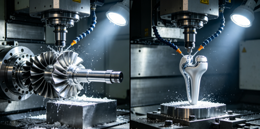
Turbine blades for aero engines and orthopedic medical implants sit at the very top of 5-axis manufacturing difficulty.
Both parts feature organic twisted freeform geometry, ultra-thin walls, hard-to-cut superalloys, and non-negotiable micron-level surface requirements.
3-axis mills force repeated re-clamping. Every fixture shift creates cumulative position error. Thin walls vibrate badly, and you end up with wavy airfoils, torn implant surfaces, and sky-high scrap rates.
At Zorapid, we run continuous 5-axis jobs on IN718 turbine components and Ti-6Al-4V ELI patient-specific implants every week. We have standardized two complete machining workflows: full simultaneous 5-axis for continuous curved profiles, plus 3+2 positioning for root and structural features.
This practical deep dive breaks down core 5-axis technology shared between turbine blade and medical implant production. We cover CAM toolpath strategy, thin-wall deformation control, material-specific cutting parameters, anti-chatter setup, and post-finishing that meets AS9100 aerospace and ISO 13485 medical standards.
We also share a real production case where single-setup 5-axis cut cycle time by 45% while holding freeform profile tolerance within ±0.008mm.
If you struggle with freeform surface inconsistency, thin-wall deflection or tool collision on complex curved parts, these shop-proven 5-axis methods will stabilize your whole production run.
Why Turbine Blades & Medical Implants Share The Same 5-Axis Machining Challenges
At first glance, engine airfoils and bone implants belong to completely different industries. But their manufacturing pain points are nearly identical.
- Continuous twisted freeform surfaces Blade airfoils have progressive twist from root to tip. Implants follow organic CT-scan bone contours. Neither can be machined with fixed vertical tool orientation. Only dynamic tilt of the tool vector keeps the cutter normal to the surface.
- Ultra-thin flexible walls Blade leading edges drop below 0.5mm thickness. Implant lattice walls and porous structures deflect easily under cutting force. Vibration creates chatter lines that ruin aerodynamic performance and biocompatible surface quality.
- High-strength difficult-to-machine alloys
- Turbine parts: Inconel 718 nickel superalloy, high heat generation, severe work hardening
- Medical implants: Ti-6Al-4V ELI titanium, low thermal conductivity, high chemical affinity that causes built-up edge
- Zero room for setup error Multi-clamp 3-axis work creates stacked deviation. Even 0.02mm misalignment breaks blade aerodynamic balance and implant assembly fit.
The only reliable fix: single-chuck 5-axis machining with continuous tool vector control.
Two Core 5-Axis Modes Used For Blades & Implants
We split all complex freeform work into two programmed strategies, matched strictly to part geometry.
1. Simultaneous Full 5-Axis (Continuous 5-Axis)
Tool and workpiece move along all 5 axes at the same time. The spindle tilts constantly to keep the ball endmill perpendicular to the curved surface.
Best application:
Twisted airfoil blade profiles, organic femoral implant contours, spine cage freeform surfaces.
- Benefits: Consistent cusp height across the entire curved surface; no visible step lines; Ra easily held below 0.4μm without hand polishing.
- Key control: Keep lead/lag angle steady between 10°–25° to avoid tool shank collision with adjacent features.
2. 3+2 Indexed 5-Axis (Positioning 5-Axis)
The rotary A/C axis locks at a fixed tilted angle, then the machine runs standard 3-axis milling.
Best application:
Blade dovetail root, implant threaded holes, edge chamfers, root fillet 清根 work.
- Benefits: Far simpler CAM programming; shorter rigid cutters eliminate chatter; heavy stock removal runs much faster.
- Rule: Use 3+2 for all prismatic structural features, save full simultaneous 5-axis only for freeform curved profiles to balance speed and accuracy.
Our standard workflow:
Roughing → 3+2 axis plunge milling for bulk material removal
Finishing → Simultaneous 5-axis contouring for all freeform curved surfaces
5 Axis Machining Technology for IN718 Turbine Blades
Step 1: CAM Toolpath Anti-Collision & Thin-Wall Protection
Blade channels are narrow, twisted, and easy to crash the tool shank into adjacent airfoils.
- Use VERICUT full machine simulation before posting G-code. We eliminate 100% of shank interference in the virtual environment first.
- Adopt spiral trochoidal roughing paths. Maintain constant chip load to avoid localized heat buildup on IN718 nickel alloy.
- For thin leading/trailing edges: Use climb milling only, limit radial depth of cut under 0.05mm per pass to reduce cutting force and wall deflection.
Step 2: IN718 Cutting Parameters (Shop Calibrated 5-Axis Data)
| Operation | Cutting Speed (SFM) | Feed Per Tooth | Axial DOC | Tool Selection |
|---|---|---|---|---|
| Rough Milling | 30–45 | 0.06–0.09 mm | 0.2–0.3 mm | AlTiN coated solid carbide bull nose mill |
| Freeform Finishing | 45–60 | 0.04–0.07 mm | 0.03–0.06 mm | Ball nose short rigid end mill |
Critical rule: Never let the tool dwell in one spot. IN718 instantly work-hardens if cutting pauses.
Step 3: Fixturing & Anti-Vibration Setup
- Use low-distortion jaw clamping only on the blade root. Never clamp the thin airfoil body.
- Minimize tool overhang to under 2× cutter diameter. Long slender tools are the top cause of blade edge chatter.
- Activate machine thermal compensation. Long 5-axis run times cause spindle thermal drift that warps profile accuracy.
Step 4: Post-Processing For Aero Engine Standards
- Remove all tool marks with abrasive flow machining (AFM) on blade root fillets
- Shot peen the airfoil surface to introduce compressive stress and improve fatigue life
- Full CMM freeform profile scanning to hold airfoil tolerance within ±0.01mm per AS9100 requirements.
5 Axis Machining Technology for Ti-6Al-4V ELI Medical Implants
Medical 5-axis work adds strict biocompatibility rules on top of freeform precision.
Step 1: CAM Path Optimization For Organic Implant Geometry
Most implants are generated from patient CT scan mesh data.
- Smooth the mesh first before generating toolpaths to avoid sharp direction reversals that create micro-vibration.
- Use constant scallop height finishing. We lock residual material below 0.002mm across the entire curved surface to eliminate manual hand sanding. Manual polishing creates micro-scratches that slow bone ingrowth and violate ISO biocompatibility rules.
- Program undercut features on acetabular cups and porous cages with continuous 5-axis tilt; no secondary EDM required.
Step 2: Titanium Alloy 5-Axis Cutting Parameters
Titanium traps heat on the cutting edge, so we run low SFM with stable chip load.
| Operation | SFM | Feed Per Tooth | Key Setting |
|---|---|---|---|
| Roughing | 50–70 | 0.07–0.10 mm | Trochoidal peeling, flood high-pressure coolant |
| Freeform Finishing | 70–90 | 0.04–0.06 mm | Ball mill, climb milling only |
Avoid low feed rates. Slow feeds create built-up edge that tears the implant surface and leaves contaminated titanium smears.
Step 3: Contamination & Deformation Control (Medical Grade Requirement)
- Dedicate a fully isolated 5-axis work cell for titanium implants. No steel chips cross-contaminate the part surface.
- Thin porous lattice structures use vacuum fixture support to hold rigidity without clamping deformation.
- Strictly limit residual stress: Run low-stress climb milling, then stress relief before final finishing to stop warpage after machining.
Step 4: Medical-Grade Post-Finishing
- Deburr all micro-edges with vibratory finishing without scratching the curved surface
- Electropolish to reach Ra ≤0.2μm, removing all micro-cracks for safe osseointegration
- Full lot traceability, dimensional FAI and surface roughness reports to meet ISO 13485 and FDA audit requirements.
5-Axis Process Comparison: Blade vs Implant
| Technical Item | Turbine IN718 Blade Machining | Ti-6Al-4V Medical Implant Machining |
|---|---|---|
| Main 5-Axis Mode | Simultaneous 5-axis for airfoil + 3+2 for root | Full simultaneous 5-axis for organic contours |
| Primary Material Risk | Work hardening & high cutting heat | BUE, heat staining & surface contamination |
| Biggest Defect | Thin-wall elastic deflection & edge chatter | Micro-scratches, residual stress warpage |
| Toolpath Focus | Anti-collision between twisted blade channels | Constant scallop for uniform biocompatible finish |
| Surface Requirement | Smooth aerodynamic profile, shot peened | Ra 0.2~0.4μm electropolished, scratch-free |
| Quality Standard | AS9100 / NADCAP | ISO 13485 / FDA 21 CFR |
| Fixturing | Root-only clamping to protect airfoil | Vacuum & low-pressure jaw clamping to avoid part distortion |
Core shared technology: Single-setup 5-axis continuous vector control + short rigid tools + climb milling + thermal error compensation.
6 Biggest 5-Axis Failures We Fix On Blades & Implants
Mistake 1: Long overhanging cutters for deep curved surfaces
Slender tools vibrate violently. Chatter creates wavy ripples on blade airfoils and implant curved faces.
Fix: Tilt the 5-axis spindle to use the shortest possible tool length.
Mistake 2: Switching between climb and conventional milling randomly
Mixed cutting directions leave uneven surface texture and variable cutting force that bends thin walls.
Fix: Lock the program strictly to climb milling for all freeform finishing passes.
Mistake 3: Ignoring thermal axis drift on long 5-axis runs
Continuous multi-hour machining heats linear axes. Freeform profile drifts out of tolerance gradually.
Fix: Turn on real-time thermal compensation for all 5 linear and rotary axes.
Mistake 4: Too high stepover on finishing paths
Wide stepover leaves visible cusps that require hand blending. Hand work ruins both aerodynamic balance and medical surface integrity.
Fix: Program constant scallop height instead of fixed stepover across all curved surfaces.
Mistake 5: Clamping thin curved sections directly in jaws
Clamping stress locks residual deformation into thin walls. After release, the blade edge warps and the implant loses its organic contour.
Fix: Only grip rigid base features; support thin sections with low-distortion fixtures.
Mistake 6: Skipping simulation before posting 5-axis G-code
Shank collision between adjacent twisted blades ruins high-value nickel alloy blanks.
Fix: Run full machine kinematic simulation in VERICUT to eliminate all interference offline.
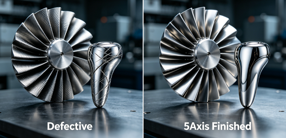
Zorapid Real 5-Axis Production Case
Project Overview
- Aerospace part: IN718 turbine compressor blade, twisted airfoil, leading edge wall thickness 0.45mm, freeform profile tolerance ±0.008mm
- Medical part: Ti-6Al-4V ELI femoral implant, organic bone contour, required Ra <0.3μm without hand polishing
Old 3+4 Multi-Setup Problems
- 3 separate re-clamping operations, profile deviation stacked up to 0.035mm
- Thin edges vibrated badly; scrap rate hit 31%
- Cycle time exceeded 22 hours per piece with repeated re-probing
Our Optimized 5-Axis Technology Upgrade
- Full single-setup simultaneous 5-axis programming with continuous tool vector tilt
- Short rigid ball endmills to eliminate chatter; climb milling only with constant chip load
- Activate 5-axis thermal compensation and real-time axis error correction
- Split roughing into 3+2 plunge milling; reserve full 5-axis only for freeform finishing
- For the titanium implant: Mesh smoothing + constant scallop finishing, no manual polishing allowed
Final Measurable Results
- Total cycle time reduced by 45%
- Freeform profile tolerance locked within ±0.007mm consistently
- Thin-wall deflection eliminated; scrap rate dropped below 0.9%
- Implant surface finished at Ra 0.26μm straight off the machine, passing electropolish biocompatibility inspection on the first run.
Quick 5-Axis Programming Checklist For Blades & Implants
Simulate all toolpaths in VERICUT to avoid shank collision
Use shortest possible cutters; limit tool overhang strictly
Lock climb milling for all freeform finishing passes
Activate machine thermal & pitch error compensation
Adopt constant scallop finishing to eliminate hand blending
3+2 axis for rough stock removal; full simultaneous 5-axis only for curved profiles
Clamp only rigid base features; never grip thin-wall curved sections
Match cutting parameters strictly for IN718 nickel alloy or Ti-6Al-4V titanium
How Zorapid Delivers Reliable 5-Axis Machining For Blades & Implants
With 20+ years of multi-axis precision manufacturing, we have dedicated 5-axis cells for aerospace turbine hardware and ISO-certified medical implant production:
- Full 5-axis DMU machining centers with high-precision rotary tables and linear scale feedback
- Offline CAM programming + full kinematic simulation to eliminate collision risk
- Material-specific adaptive toolpaths for IN718, Ti-6Al-4V ELI, cobalt chrome and PEEK
- Thin-wall anti-chatter fixturing and low-stress machining sequences to control deflection
- CMM freeform scanning + surface roughness testing to validate profile and Ra before shipment
- Strict batch compliance: AS9100 for aerospace parts, ISO 13485 clean production for medical implants
We bridge aerospace turbine technology and medical implant precision with standardized 5-axis workflows, cutting trial-and-error scrap and shortening lead times.
Conclusion
Turbine blades and medical implants rely on the same core 5-axis manufacturing technology: single-setup continuous tool vector control, anti-chatter rigid tooling, constant chip load climb milling, and strict error compensation.
Three key takeaways for stable production:
- Split your workflow: Use 3+2 indexed 5-axis for fast roughing, and reserve full simultaneous 5-axis only for twisted freeform curved surfaces.
- Eliminate multi-clamp repositioning entirely. One single chuck removes all cumulative profile error.
- Match toolpath, coolant and cutting parameters to your alloy — nickel superalloys need low heat generation, while titanium requires stable chip load to avoid BUE and surface staining.
When you control tool tilt, vibration and thermal drift, you can consistently hold micron-level freeform accuracy on both engine airfoils and patient-specific implants.
Send your blade or implant STEP files to Zorapid today. Our 5-axis programming team will build collision-free toolpaths and quote your batch within 24 hours.
FAQ
What is the difference between 3+2 axis and full simultaneous 5-axis for turbine blades?
3+2 locks the rotary axis at a fixed tilt angle for heavy roughing and root feature work. Simultaneous 5-axis continuously tilts the spindle to follow twisted airfoil contours. We combine both to balance cycle speed and surface quality.
How do I stop thin turbine blade edges from deflecting during 5-axis milling?
Use short rigid ball mills, limit depth of cut per pass, run climb milling with low cutting force, and never clamp the thin airfoil section. Tool overhang is the biggest source of edge chatter and wall deflection.
Can 5-axis machining produce implant surfaces ready for electropolish with zero hand sanding?
Yes. With constant scallop height finishing and stable 5-axis tool vector control, we hold Ra <0.3μm directly off the mill. Manual polishing is eliminated, protecting the implant’s biocompatible surface integrity per ISO 13485.
What SFM should I run for IN718 5-axis blade finishing?
Stick to 45–60 SFM with low feed per tooth. Higher speed creates excessive heat and rapid work hardening on nickel superalloys. High-pressure through-tool coolant is mandatory.
Can I machine blisk integral rotors and custom orthopedic implants on the same 5-axis machine?
Yes, with dedicated fixturing and separate work cells to avoid cross-contamination. We run both aerospace and medical freeform parts on the same 5-axis equipment with separate programming and cleaning protocols.