Geometric Dimensioning and Tolerancing (GD&T) is essential for manufacturing perfectly fitting parts. It defines accurate dimensions and geometric shapes and helps reduce errors throughout the manufacturing process.
GD&T makes it easier to produce high-quality components that fit and function together seamlessly, lowering costs and saving lead time. It is especially valuable in industries including aerospace, automotive, and custom precision machining.
Several Key Factors of Geometric Dimensioning and Tolerancing in Manufacturing
Improved Communication
GD&T provides a standardized technical language that minimizes errors and misunderstandings among designers, process planners, and manufacturers. By clearly defining allowable variations on part drawings, GD&T ensures everyone involved in the product development process stays aligned.
Enhanced Functionality
GD&T focuses on the functional performance of parts, guaranteeing proper assembly and intended operation. By precisely controlling part geometry, GD&T helps eliminate issues such as misalignment, poor fit, and mechanical failure.
Cost Reduction
Implementing GD&T significantly cuts costs by reducing scrap, rework, and quality claims. By ensuring parts meet exact specifications right from the first production run, GD&T minimizes the need for costly corrections.
Higher Efficiency
GD&T delivers clear guidelines for machinists and inspectors to streamline the entire production workflow. With standardized GD&T symbols and tolerances, manufacturers can quickly grasp design intent and produce components that meet required specifications efficiently.

How Geometric Dimensioning and Tolerancing Works
GD&T utilizes a system of symbols and feature control frames on the shop floor to define permissible variations in part drawings. These basic elements work together to specify how much a part can deviate from its nominal dimensions while still maintaining proper functionality.
GD&T symbols represent various geometric controls such as flatness, straightness, and circularity. Feature control frames contain specific tolerance values for each referenced feature. These symbols and frames are placed on engineering drawings or 3D models to clearly and consistently convey the design intent.
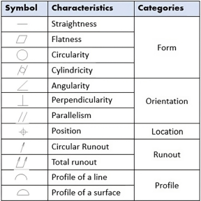
Common GD&T Symbols and Their Meanings
In GD&T, symbols play a key role in communicating geometric tolerances on engineering drawings. Each symbol represents a specific type of geometric control. Understanding these symbols is essential for correctly interpreting and applying GD&T. Below are the most commonly used GD&T symbols:
Straightness
The straightness symbol defines the permissible deviation of a feature such as a line or axis from a perfectly straight path. It ensures the feature stays within a specified tolerance zone, which is critical for components that require smooth installation or movement during assembly.
Flatness
The flatness symbol controls permissible variation in the flatness of a surface, ensuring all points on the surface lie between two parallel planes. It is especially important for reliable sealing and tight contact between mating housing parts.
Circularity (Roundness)
The circularity symbol regulates the roundness of features such as holes and shafts. It keeps the feature within a defined tolerance zone and is vital for components that rotate or fit into mating assemblies.
Cylindricity
Cylindricity combines straightness and circularity to control the overall permissible variation of cylindrical features. This symbol is used when both the roundness and axial straightness of a part are critical to its function.
Profile of a Surface
The profile of a surface symbol controls allowable variation in the shape of a surface, ensuring it conforms to the designated contour within the tolerance zone. It is widely used for complex curved housings where precise shape retention is essential for part functionality.
Profile of a Line
Similar to profile of a surface, the profile of a line symbol governs permissible variation in linear shape, ensuring the feature follows the defined contour within the tolerance zone. It is commonly used to control edges and boundaries on mechanical parts.
Angularity
The angularity symbol controls the angular deviation of a feature relative to a datum. It ensures the feature remains within the tolerance zone at the required angle, which is critical for components that must align at a specific angle in an assembly.
Perpendicularity
Perpendicularity controls the 90‑degree relationship between two features, such as a surface and an axis. It guarantees components join at precise right angles, a common requirement in mechanical assembly.
Parallelism
The parallelism symbol limits permissible variation in parallel alignment between two features, keeping them within the specified tolerance zone. It is essential for parts that need to slide or fit smoothly while maintaining parallel alignment.
Position
The position symbol is one of the most complex and widely used symbols in GD&T. It controls the allowable positional deviation of a feature relative to datums, ensuring the feature stays within its tolerance zone. It is particularly critical for accurate assembly of parts with multiple mounting features.
Concentricity
Concentricity controls the permissible deviation of a feature’s centerline relative to a datum axis. It is applied to features that must remain centered with reference to other components, such as shafts inside bearings.
Symmetry
The symmetry symbol regulates permissible symmetrical deviation of a feature relative to a datum plane. It is highly important for components requiring balanced layout and central alignment.
Every GD&T symbol plays a vital role in defining allowable geometric variation of part features. They ensure parts function as intended even with minor manufacturing deviations.
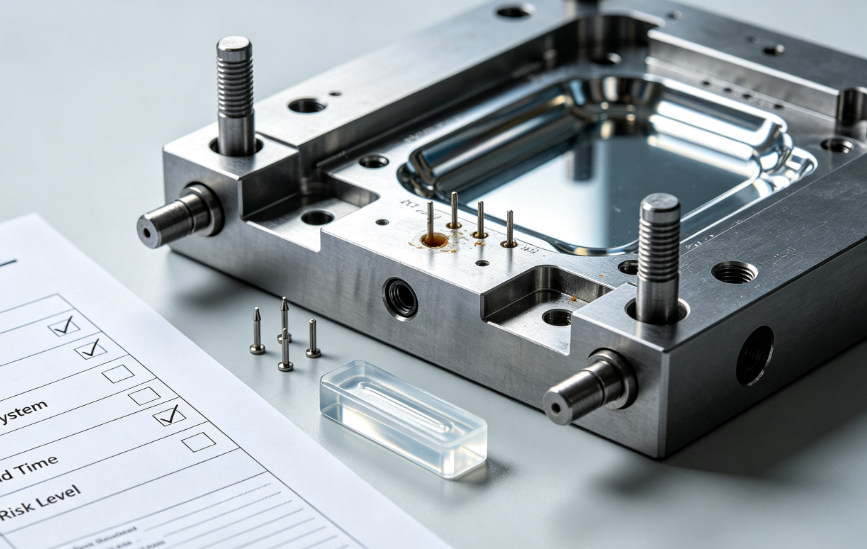
Tolerances in CNC Machining
The Role of Tolerances in CNC Machining
Tolerances are critical in CNC machining to achieve the required precision and perfect fit of mechanical parts.
CNC machines operate with high accuracy, and GD&T helps ensure manufactured parts conform to design intent and function properly.
By specifying precise tolerances, GD&T reduces the risk of part failure and guarantees accurate assembly.
ISO 2768-f vs ISO 2768-m
ISO 2768 is a widely adopted standard that defines general tolerances for CNC machining.
The standard includes multiple tolerance grades, among which ISO 2768-f (fine) and ISO 2768-m (medium) are the most commonly used.
Fine tolerances apply to high-precision machining requirements, while medium tolerances are suitable for less demanding applications.
The selection of appropriate tolerance grades depends on part service requirements and the capability of the machining process.
GD&T Tolerance Guidelines
When applying GD&T to CNC machined parts, it is necessary to consider the capability and limitations of the machining process.
Factors such as machine precision, tool wear, and material characteristics all affect achievable tolerance levels.
Selecting the proper tolerance standard — such as ISO 2768-f or ISO 2768-m — is essential to ensure parts meet design specifications without compromising manufacturability.
Tolerance Stack-Up Analysis
Tolerance stack-up analysis is a core concept in GD&T, especially for assembly projects.
It calculates the cumulative effect of individual feature tolerances on the overall assembly.
Proper tolerance stack-up analysis ensures the final assembly meets dimensional specifications and operates as designed.
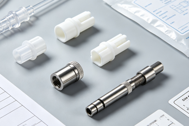
Rapid Prototyping and Part Manufacturing with CNC Machining
GD&T plays a critical role in rapid prototyping and manufacturing, especially in CNC machining. Learn more about CNC machining advantages: https://zorapid.com/cnc-machining. By applying GD&T in CNC machining, planners and manufacturers can quickly and directly produce prototypes and final parts that meet strict design specifications. This precision is vital during validation, as even small deviations can cause major issues with part functionality or assembly.
With CNC machining, translating GD&T specifications from design to production is straightforward, enabling fast prototype iteration and improvement. This efficiency not only accelerates development cycles but also ensures the final product closely matches the original design intent, minimizing the need for costly adjustments or rework.
The ability to rapidly prototype using GD&T allows planners to evaluate the fit, form, and function of parts in real‑world conditions. In this way, potential issues can be identified and resolved early in the development process, reducing the risk of product failure. The combination of GD&T and CNC machining provides planners with an essential set of tools to deliver high‑quality products quickly and efficiently.
Application of GD&T in Various Industries
Geometric Dimensioning and Tolerancing (GD&T) is widely adopted across industries due to its precision, clarity, and effectiveness in ensuring part functionality. Beyond traditional manufacturing, it is highly applicable in sectors where precision is critical, including aerospace, automotive, medical devices, and electronics.
Aerospace Industry
In the aerospace sector, where safety and performance are paramount, GD&T is essential to guarantee all components fit perfectly and operate reliably under extreme conditions. Parts used in aircraft and spacecraft require rigorous inspection, and GD&T provides the necessary framework for controlling critical dimensions and tolerances that directly impact performance and safety.
Learn more about aerospace parts: https://zorapid.com/aerospace
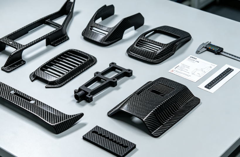
Automotive Industry
The automotive industry also relies heavily on GD&T to ensure parts are interchangeable, assemble correctly, and perform as intended. GD&T helps control tolerances for critical components such as engine parts, transmissions, and body panels, ensuring vehicles meet strict performance and safety standards.
Learn more about automotive parts: https://zorapid.com/automotive-industry
Medical Industry
In the medical device sector, precision is critical to ensuring the safety and effectiveness of equipment used in patient care. GD&T is used to control the quality of components such as implants, surgical instruments, and personal care devices, ensuring they meet strict requirements for accuracy and reliability.
Learn more about medical parts: https://zorapid.com/medical
Electronics Industry
The electronics industry also benefits from the use of GD&T, particularly in the manufacturing of printed circuit boards (PCBs) and microelectronic components. GD&T helps control tolerances for features critical to the proper function of electronic assemblies, such as connector pins, solder pads, and component placement.
Consumer Products
In consumer products, where aesthetics and ergonomics are often important, GD&T plays a key role in ensuring parts fit correctly and perform as intended. From household appliances to consumer electronics, GD&T helps maintain the quality and reliability of products people use every day.
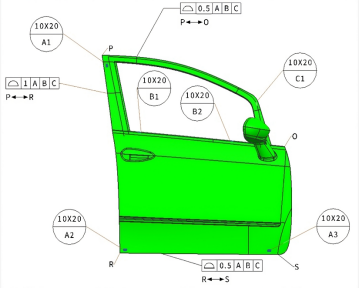
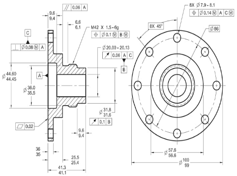
GD&T in Part Design (Examples)
Conclusion
Geometric Dimensioning and Tolerancing (GD&T) is an indispensable tool in modern engineering and manufacturing. It provides a standardized technical language to define and communicate permissible variations in part geometry. By ensuring components conform to design intent and function reliably in final assembly, GD&T plays a vital role in maintaining manufacturing quality, precision and operational reliability.
This guide offers a comprehensive overview of GD&T, covering its fundamental principles, standard symbols, governing rules, and practical applications across a wide range of industries. Whether you are an experienced engineer or a beginner in product development, understanding and applying GD&T is essential to achieving design success and consistent product quality.
By mastering GD&T principles, you can improve the clarity of engineering definitions, reduce manufacturing errors and rework, and ensure your components meet the highest standards of precision and performance. In an industry where accuracy and credibility grow increasingly critical, GD&T equips you with the essential tools to succeed in engineering and manufacturing.
FAQ
What are the risks without GD&T?
Basic dimensions cannot control perpendicularity, concentricity, flatness and other geometric deviations. Parts may pass dimensional check but fail assembly, cause jitter and accelerated wear.
hat benefits does GD&T bring to CNC precision machining?
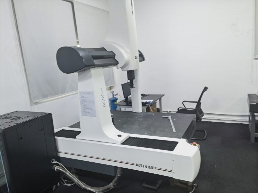
Clear tolerance definition and well-defined machining datums guide process planning. It enables accurate CMM inspection, improves yield, stabilizes precision and cuts communication costs.
How does Zorapid follow the GD&T process?
We conduct DFM tolerance review upon drawing receipt and identify critical geometric requirements. Machining adopts unified datum strategy, and finished parts are fully inspected by CMM per GD&T specifications for full compliance.
Do prototype parts also need GD&T?
Yes. High-fit prototypes intended for mass production iteration must follow GD&T to ensure repeatable manufacturing and consistent assembly in later volume runs.