
Published:Zorapid.Ltd
Aluminum alloys (6061-T6, 7075-T6, 5052) feature high ductility and low elastic modulus. Thin ribs, deep pockets, lightweight airframe walls and battery tray frames deflect easily under cutting pressure.
Two linked scrap risks destroy dimensional accuracy and surface quality:
- Chatter: Resonance vibration between cutting tool, workpiece and machine frame. Creates visible wave ripples on aluminum surfaces, ruins Ra finish and accelerates tool breakage.
- Thin-wall deformation / springback: Cutting force pushes thin aluminum walls outward during machining; after part release, residual stress pulls geometry out of tolerance, causing consistent GD&T failure.
Generic high-feed roughing, long overhang tools and weak single-sided fixturing amplify both defects. This guide covers design, fixturing, tooling, parameter and toolpath fixes proven to stabilize thin aluminum CNC batches for aerospace, EV and automation hardware.
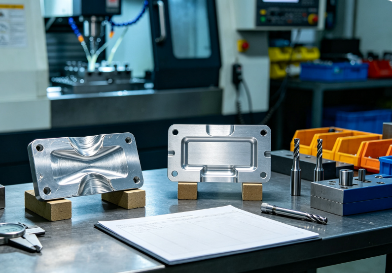
Root Cause Breakdown: Chatter vs Thin-Wall Deformation
Chatter Vibration Core Causes
- Long, slim end mill overhang creating low tool rigidity
- Unmatched spindle speed hitting natural resonance frequency of blank/fixture
- Heavy single-pass radial cutting load generating high lateral force
- Loose tool holders, worn spindle bearings or thin unsupported workpiece sections
- High helix tools generating uneven side pressure on thin aluminum walls
Thin-Wall Deformation Core Causes
- Wall height-to-thickness ratio exceeding 8:1 without support ribs
- Unbalanced material removal releasing internal blank residual stress
- Heavy roughing single-pass load bending thin ribs outward
- One-sided clamping creating uneven holding pressure
- Missing stress relief before finish machining; post-machining warpage days after production
DFM Design Adjustments to Prevent Thin-Wall Deflection Upfront
Design tweaks deliver the biggest long-term reduction of scrap, before any machining begins:
- Control wall height-to-thickness ratio Max safe ratio ≤6:1 for 7075 high-strength aluminum; ≤8:1 for softer 6061. If taller walls are required, add reinforcing gusset ribs every 20–30mm span.
- Add generous internal radii ≥0.8mm Sharp 90° corners concentrate stress and amplify cutting force deflection; smooth radii distribute load evenly across thin walls.
- Symmetrical geometry balancing Even material removal on opposite sides of thin walls avoids one-sided stress release that pulls geometry out of square.
- Temporary sacrificial support tabs Design small connecting tabs linking thin walls to main stock blank; tabs are trimmed off in a final light finishing pass. Eliminates free-standing unsupported thin ribs during roughing.
- Uniform wall thickness Avoid sudden thick-to-thin wall transitions; step thickness gradually to prevent localized stress hotspots.
- Reserve thick datum bosses for clamping Locate all fixture contact points on heavy solid stock sections, never directly on thin functional walls.
Rigid Fixturing Workarounds for Fragile Aluminum Thin Walls
Weak holding lets thin aluminum vibrate and bend under cutting force; use these high-stability clamping methods:
- Vacuum chuck full-surface holding For flat thin sheet blanks and shallow pocket housings: full vacuum adsorption eliminates localized clamp pressure deformation. Add sealing grooves to avoid air leakage.
- Zero-point fixture modular hard jaws with wide contact pads Distribute clamping force over large surface areas instead of narrow edge bites that dent thin aluminum.
- Backing support filler (low-melt alloy / removable epoxy) Inject low-temperature filler into hollow thin-wall cavities before machining; filler acts as rigid internal support during cutting, melted out post-process. Ideal for deep hollow enclosures.
- Dual-sided symmetric clamping Clamp thin wall blanks from two opposite sides to counteract lateral cutting push force. Single-side jaw clamping always creates deflection.
- Custom sacrificial fixture nests Machine matching aluminum nest contours to fully support the backside of thin ribs during roughing.
Tool & Holder Selection to Suppress Chatter Vibration
Tool rigidity is the fastest chatter fix for aluminum thin-wall machining:
- Shortest possible tool overhang Minimize extension length from tool holder to cutting tip; every extra 10mm overhang doubles vibration risk. Use shrink-fit holders for maximum grip rigidity.
- Solid carbide high-stiffness end mills Avoid HSS or long-reach indexable inserts. 2-flute or 3-flute solid carbide tools work best for aluminum chip evacuation.
- Reduce tool helix angle for thin walls Low helix (30°–35°) tools cut down lateral side thrust force that pushes thin aluminum walls sideways. High helix (45°+) generates heavy side load and springback.
- Damped anti-vibration tool holders For unavoidable long overhang deep pocket machining; internal vibration damping absorbs resonance chatter.
- Match tool diameter to pocket width Use largest feasible end mill to reduce number of cutting passes and lateral side load on thin adjacent walls.
Optimized Aluminum Cutting Parameters to Reduce Cutting Force
Heavy depth of cut and aggressive feeds create bending force on thin aluminum walls; adjust parameters for light, consistent chip load:
- Lower radial stepdown (side cut depth) Limit radial engagement to ≤30% of tool diameter for thin wall areas; full-width slotting generates extreme lateral push force and chatter.
- Moderate axial depth of cut, split into multiple light passes Instead of single full-depth roughing, split axial removal into 2–3 shallow passes to reduce wall bending load.
- Optimize spindle speed to avoid resonance chatter Run spindle speed 20–30% above or below the observed chatter frequency; test small RPM increments to locate vibration-free stable zones.
- High feed per tooth, light chip load Thin uniform chips reduce peak cutting force vs deep heavy chip loads that deflect walls. Aluminum works well with fz = 0.12–0.20mm/tooth stable light feeds.
- Abundant flood coolant Coolant lubricates cutting edge to lower friction force; thermal expansion difference also reduces vibration resonance risk. Dry machining amplifies chatter on thin aluminum.
Toolpath Optimization to Minimize Thin-Wall Springback & Chatter
Default CAM linear roughing paths generate uneven side load; these toolpath strategies stabilize thin aluminum geometry:
- Trochoidal adaptive roughing Constant small radial chip load eliminates sudden heavy side cuts that bend thin walls. Oscillating path evenly distributes cutting force to avoid deflection and chatter ripples.
- Outside-in roughing sequence for pockets Machine pocket material from outer perimeter inward, never cut thin wall sides first. Leaves solid stock supporting thin ribs during roughing.
- Separate rough & finish passes with stock allowance buffer Leave uniform 0.1–0.15mm finish stock on all thin walls; roughing removes bulk material without touching final functional geometry, avoiding permanent deflection during heavy stock removal.
- Climb milling only (down-milling) Conventional up-milling creates impact shock at tool entry, triggering chatter and wall bending. Climb milling delivers smooth, consistent cutting force with minimal lateral push.
- Continuous contour finishing without full retracts Eliminate repeated rapid retracts and re-entry shock on thin wall surfaces; one uninterrupted finish pass reduces vibration marks.
Stress Relief & Post-Machining Stabilization Processes
Even perfect machining leaves residual stress that warps thin aluminum parts after unclamping:
- Vacuum stress relief before finish machining For 7075 aerospace thin-wall parts: heat treat blank at 120–150°C for 2–4 hours, slow cool. Releases casting/forging residual stress before removing thin wall stock.
- Partial roughing + intermediate stress relief Rough out 80% of material, send to stress relief furnace, then run light finish passes on stabilized blank. Cuts post-machining warpage by over 70% on ultra-thin rib structures.
- Slow cooling cycle after machining Leave parts clamped in fixture for 30–60 minutes post-cut to normalize temperature before release; sudden temperature change creates thermal distortion.
- Light tumble deburr only Aggressive heavy media tumbling bends fragile thin aluminum walls; use soft micro media for edge deburring without mechanical deformation.
Real Client Case: 7075 Aerospace Thin-Wall Aluminum Housing Fix
An aerospace Tier 1 machined 7075-T6 lightweight equipment housings with 1.2mm thin walls, height-to-thickness ratio 9:1.
Original Defect Pain Points
- Severe chatter wave ripples on all vertical thin walls, failed surface roughness specs
- 0.04–0.07mm outward springback after unclamping, positional GD&T out of tolerance
- High scrap rate (28%) from thin wall deflection and visible vibration marks
- Long 50mm tool overhang required for deep pocket geometry
Implemented Full Optimization Package
- DFM redesign added 0.6mm reinforcing gussets to lower wall ratio to 5.5:1, sacrificial support tabs integrated on all rib edges
- Switched to shrink-fit short-overhang 3-flute low-helix carbide end mill with damped anti-vibration holder
- Trochoidal outside-in roughing, radial stepdown limited to 25% tool diameter, climb milling only
- Intermediate vacuum stress relief after roughing before finish machining
- Custom vacuum full-surface fixture with backing epoxy filler for hollow cavities
Final Outcome
Zero chatter ripple defects, thin wall deflection reduced to ≤0.008mm, scrap rate dropped to 1.1%, consistent pass on all CMM GD&T inspection batches.
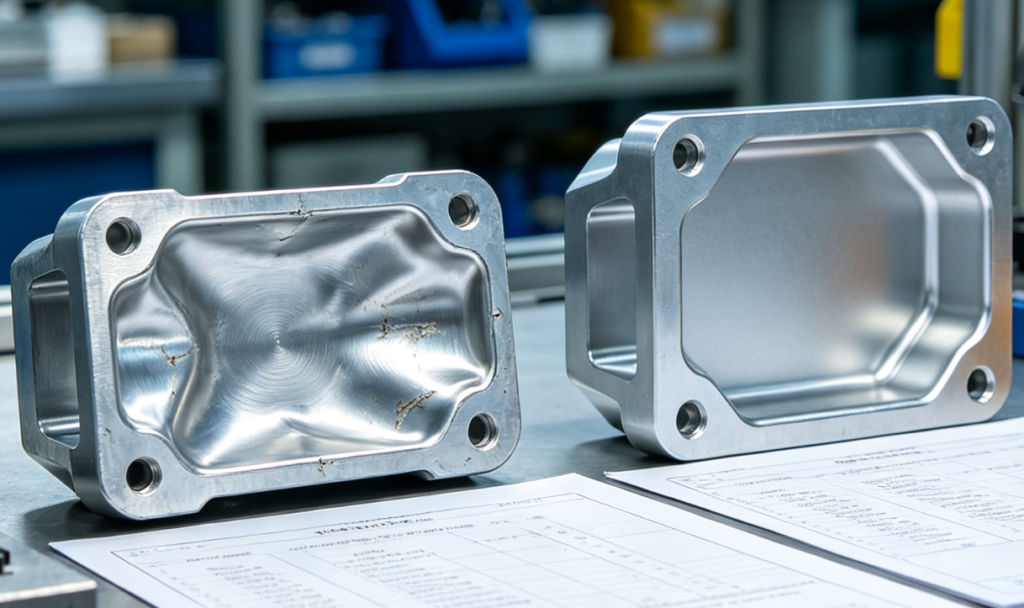
Step-by-Step Troubleshooting Checklist for Chatter & Deformation
Run this sequence when aluminum thin-wall parts show vibration or dimensional drift:
- Visual check: Identify if defects are surface chatter ripples, or post-unclamp warpage
- Tool audit: Shorten tool overhang, switch to solid carbide low-helix end mill, tighten shrink holder
- Fixture audit: Add vacuum backing or internal filler support; use dual-sided symmetric clamping
- CAM toolpath fix: Enable trochoidal adaptive roughing, switch to climb milling, reduce radial stepdown
- Parameter test: Adjust spindle RPM to avoid resonance zone, lower radial cut depth, increase coolant flow
- Process check: Add intermediate stress relief between rough and finish machining
- DFM review: Add support ribs, sacrificial tabs, increase wall thickness ratio if design allows
Common Costly Mistakes That Worsen Aluminum Thin-Wall Scrap
- Mistake: Full-width slotting roughing on thin adjacent walls Fix: Limit radial engagement to ≤30% tool diameter, use trochoidal paths
- Mistake: Long overhang indexable tools for deep thin pocket machining Fix: Short solid carbide shrink-fit tools with anti-vibration holders
- Mistake: Roughing thin functional wall geometry down to final size in one pass Fix: Leave 0.1–0.15mm finish stock, separate rough and finish operations
- Mistake: Single-sided narrow jaw clamping on large thin aluminum blanks Fix: Full vacuum chuck or dual-sided wide contact symmetric clamping
- Mistake: Skip stress relief and machine full geometry in one continuous run Fix: Partial roughing + intermediate stress relief for high-strength 7075 thin walls
- Mistake: High helix 45°+ end mills for tall thin ribs Fix: Switch to 30–35° low helix to cut lateral side thrust deflection
FAQ
What wall thickness ratio is safe for 7075 aluminum without deflection?
Max stable ratio 6:1 for 7075-T6 without support ribs; add gussets if taller walls are required. Softer 6061 allows up to 8:1 ratio.
Is climb milling always required to eliminate chatter on thin aluminum?
Yes. Conventional up-milling creates impact shock at tool entry that triggers vibration and wall bending; climb milling delivers smooth, low-thrust cutting.
Can stress relief fully eliminate post-machining thin-wall warpage?
Intermediate stress relief after roughing removes most bulk residual stress; combined with light finish passes, warpage can be controlled below 0.01mm for aerospace tolerances.
Which tool helix angle minimizes thin aluminum wall springback?
Low helix 30°–35° solid carbide end mills reduce lateral side pushing force vs standard 45° high-helix tools.
How to fix chatter if deep pockets force unavoidable long tool overhang?
Use internal damped anti-vibration tool holders, split axial cuts into multiple shallow passes, and lower radial stepdown to reduce side load vibration.
Wrap-Up
Chatter vibration and thin-wall deformation stem from three core root causes: weak tool rigidity, excessive lateral cutting force, and unrelieved residual blank stress. The most cost-effective fix starts at DFM design by limiting wall height-to-thickness ratios and adding temporary sacrificial support tabs.
Rigid short-overhang carbide tooling, symmetric vacuum backing fixturing, trochoidal climb milling toolpaths and light limited radial stepdowns work together to suppress cutting force deflection during machining. Intermediate vacuum stress relief eliminates delayed post-unclamping warpage that ruins dimensional tolerances days after production.
Zorapid’s aerospace CNC workflow integrates all these controls for thin-wall 6061 / 7075 aluminum housings and brackets. We run DFM wall ratio reviews upfront, use anti-vibration tooling and adaptive roughing paths, and apply standardized stress relief cycles to deliver chatter-free, dimensionally stable thin aluminum batches for EV, aerospace and automation OEMs.
Request Free Thin-Wall Aluminum DFM & Process Optimization Review
Share your aluminum part CAD, alloy grade, wall thickness dimensions and target GD&T tolerances. Our CNC engineering team will flag deflection/chatter risk zones, provide DFM redesign suggestions and simulate optimized chatter-suppressing toolpaths for stable low-scrap production.


