Published:Zorapid.Ltd
Aircraft gas turbine hot sections operate under brutal conditions: extreme heat, continuous cyclic loading, oxidation, and thermal fatigue. For decades, Inconel nickel-based superalloys (IN718, IN625) have been the material of choice for turbine discs, blades, nozzles, combustor hardware, and fuel injectors.
But anyone working with Inconel quickly learns one hard truth:
This superalloy is notoriously difficult to manufacture.
Low thermal conductivity, rapid work hardening, high cutting forces, and tendency to form built-up edge destroy cutting tools during machining. For additive manufacturing, steep thermal gradients create residual stress, distortion, and risk of microcracking.
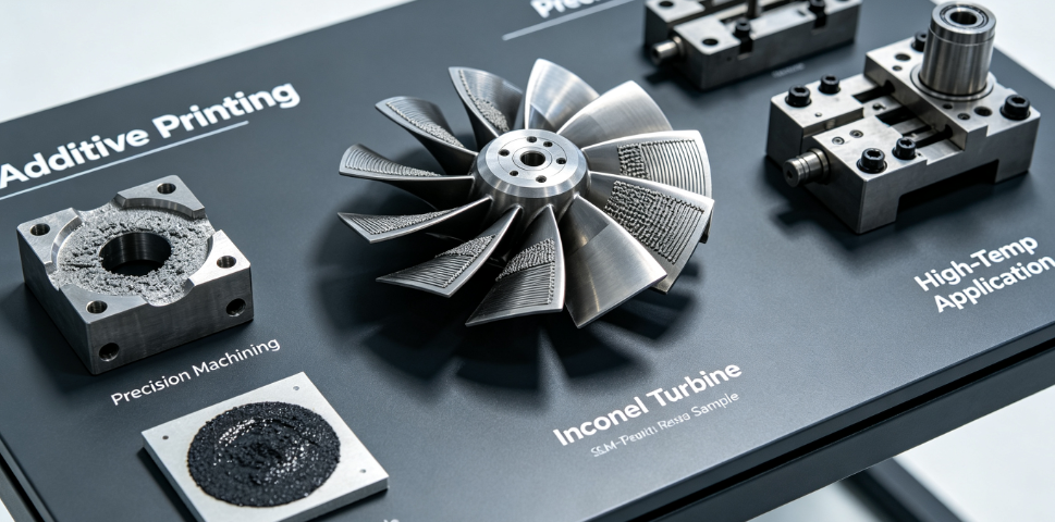
Today’s turbine engineers no longer rely solely on traditional CNC machining. SLM (Selective Laser Melting) metal printing unlocks revolutionary designs — conformal cooling channels, topology optimized lightweight structures, and monolithic assemblies impossible to mill from solid billet.
In this guide, we break down the fundamentals of both high-precision CNC machining and SLM printing for Inconel aircraft turbine components. We compare use cases, expose common failure modes, and explain how Zorapid delivers consistent, aerospace-grade Inconel parts for turbine R&D and low-volume production.
Why Inconel Is Irreplaceable For Aircraft Turbine Hot Sections
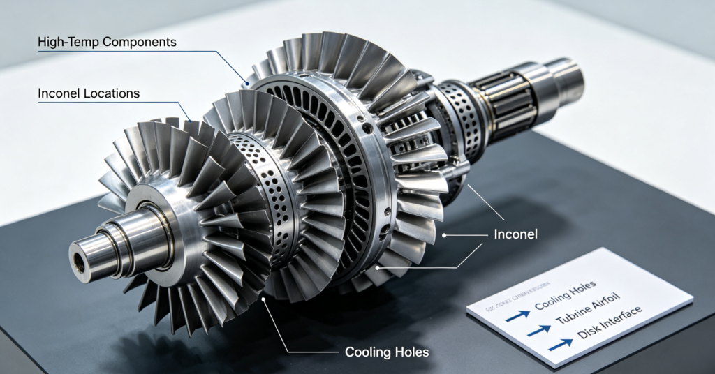
Inconel 718 and Inconel 625 retain high tensile strength, creep resistance, and oxidation stability at continuous operating temperatures up to 650°C–700°C. When exposed to extreme heat, most steels and aluminum alloys soften rapidly, but nickel superalloys maintain structural integrity.
Typical turbine components manufactured from Inconel:
- Turbine discs, blisks, and rotor hubs
- Turbine nozzle guide vanes & airfoils
- Combustor liners, transition pieces
- Fuel nozzles and injection assemblies
- Exhaust frames, mounting brackets, heat shields
- Turbine blade cooling inserts
Key material challenges that define every manufacturing strategy:
- Very low thermal conductivity – heat stays trapped at cutting/melting zones
- Severe work hardening under mechanical stress
- High ductility leads to built-up edge (BUE) during machining
- Complex precipitation microstructure sensitive to heat treatment cycles
- Thermal mismatch creates distortion after machining or SLM printing
Precision CNC Machining of Inconel Turbine Components
CNC machining from forged or rolled Inconel billets remains the gold standard for high-load rotating parts such as turbine discs, blisk root profiles, and critical mating interfaces. Wrought Inconel delivers stable, homogeneous microstructure with well-understood fatigue performance.
Core Machining Challenges
- Standard cutting speeds lead to catastrophic tool wear
- Thin-walled combustor features deflect under heavy cutting loads
- Surface damage, residual stress, and micro-notches reduce high-cycle fatigue life
- Fir-tree blade root profiles demand ultra-tight profile tolerances and superior surface integrity
Shop-Proven Machining Best Practices for Turbine Hardware
- Use trochoidal / adaptive clearing roughing Avoid full-width slotting. Light, consistent radial engagement limits cutting force, reduces heat buildup and prevents premature work hardening.
- Rigid machine setup and short tool overhang Vibration creates chatter marks that act as fatigue initiation sites — unacceptable for rotating turbine parts.
- Specialized tooling + high-pressure through-spindle coolant Coated carbide or whisker-reinforced ceramic inserts are preferred. Flood coolant directly flushes heat away from the cutting edge. Dry machining is strongly discouraged for critical surfaces.
- Pre-machining stress relief Forged Inconel stock carries residual stress. Stress-relief cycles before roughing and between rough/finish passes minimize post-machining distortion.
- Climb milling for all finishing operations Improves surface finish, reduces work hardening layer thickness and avoids surface tearing.
- Control final surface roughness Critical turbine mating surfaces typically require Ra ≤0.8 μm. Abrasive hand finishing is restricted; mechanical polishing must be tightly controlled to avoid introducing embedded contaminants.
Best for: Turbine discs, blisks, fir-tree blade roots, thick structural components, parts requiring certified wrought material microstructure.
SLM / LPBF Additive Manufacturing of Inconel Turbine Parts
SLM metal printing builds components layer-by-layer using fine Inconel powder. It removes nearly all geometric limitations of subtractive manufacturing. For modern turbine efficiency upgrades, this technology is transformative.
Biggest SLM Advantages for Turbine Designers
Monolithic components replace multi-part welded assemblies
Integrated conformal cooling channels and internal film cooling hole networks
Topology optimization reduces component weight without sacrificing strength
Rapid prototype iteration for aerodynamic and thermal testing
Fabricate complex internal geometries impossible to machine from solid
Critical SLM Manufacturing Risks You Must Manage
- High residual stress from rapid heating and cooling → part warpage and cracking
- As-built anisotropic mechanical properties
- Internal porosity risk if process parameters are poorly tuned
- Rough as-built surface finish requires extensive post-processing
- Unsupported overhangs create surface defects and need careful build orientation planning
Mandatory Post-Processing Workflow for SLM Inconel Turbine Parts
No SLM part is ready for turbine service straight off the build plate:
- Stress relief heat treatment directly after printing
- HIP (Hot Isostatic Pressing) – closes internal porosity for high-cycle applications
- Solution annealing + aging to achieve target mechanical properties
- Wire EDM removal from build plate
- 5-axis CNC finish machining on all datum surfaces, sealing faces and airfoil edges
- Precision drilling / EDM micro-hole machining for film cooling features
- Surface finishing, cleaning and non-destructive testing (NDT)
Best for: Fuel nozzles, turbine vanes with complex cooling geometry, lightweight static components, R&D prototype airfoils, topology optimized brackets.
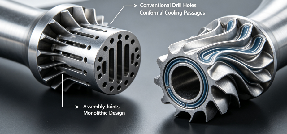
CNC Machining vs SLM Printing for Inconel Turbine Components
Core Performance & Capability Comparison
| Comparison Item | CNC Machining (Wrought Inconel) | SLM Additive Manufacturing |
|---|---|---|
| Raw Material Form | Forged / rolled billet | Gas-atomized Inconel powder |
| Geometric Freedom | Limited; complex internal features cannot be produced | Excellent; internal cooling channels, lattice, monolithic assemblies |
| Microstructure | Homogeneous wrought grain structure, low fatigue risk | Fine dendritic as-built microstructure; HIP + heat treatment required |
| Lead Time for First Article | Medium (stock procurement + machining) | Longer (build setup, printing, mandatory post-processing chain) |
| Ideal Volume Range | Low to high serial production | Prototypes, low-to-medium batch, custom R&D hardware |
| Surface Integrity (As-produced) | Excellent controlled finish | Rough as-built surface; finish machining required |
| Typical Tolerance Potential | ±0.005 mm on critical features | ±0.03~0.05 mm as-built; ±0.005 mm after 5-axis finishing |
| Material Traceability | Straightforward for certified wrought stock | Requires full powder batch, build log, heat treatment documentation |
Application Fit & Limitation Summary
| Comparison Item | CNC Machining (Wrought Inconel) | SLM Additive Manufacturing |
|---|---|---|
| Rotating Critical Parts (Discs, Blisks) | Preferred standard solution | Limited; requires full material qualification |
| Static Hot Section Hardware | Suitable for simple geometry | Superior for complex cooling geometry |
| Weight Optimization Potential | Restricted by billet stock limits | Very high via topology optimization |
| Upfront Investment | Tooling fixturing only | Powder, machine time, HIP & heat treatment capacity |
| Risk of Internal Defects | Very low with certified forgings | Porosity risk if process control is weak |
| Design Iteration Cost | High; every new geometry requires re-fixturing | Low; modify CAD file directly |
Most Common Costly Inconel Manufacturing Defects for Turbine Hardware
- Work-hardened surface layers from improper machining parameters Creates hidden fatigue initiation points on airfoils and blade roots.
- Residual stress leading to dimensional drift after machining / printing Parts pass initial inspection, then deform days or weeks later.
- SLM microcracking from poor scan strategy or insufficient preheating Catastrophic failure risk under cyclic turbine loads.
- Poor surface finish and chatter marks Lower component service life in hot vibrating environments.
- Improper heat treatment cycles Wrong aging temperatures shift tensile, creep and fatigue properties away from specification.
- Trapped powder inside SLM internal cooling channels Loose powder can break free during turbine operation and damage downstream hardware.
What Makes Zorapid a Trusted Partner for Inconel Turbine Components
Many manufacturers can machine or print Inconel. Few understand the strict demands of aerospace turbine hot-section hardware. Zorapid combines 5-axis precision CNC machining and SLM additive manufacturing under one roof, supporting you from R&D prototype through pilot qualification batches.
Dual manufacturing capability for Inconel
We offer both wrought Inconel 5-axis machining and SLM Inconel printing. Our engineers provide unbiased process recommendations based on your geometry, load case, volume target and budget — no push toward a single service.
Aerospace-validated Inconel process libraries
Locked, refined parameters for IN718 and IN625. For machining: optimized trochoidal toolpaths, coolant strategy and stress management. For SLM: controlled scan strategies to minimize residual stress and porosity risk.
Full post-processing ecosystem for turbine-grade quality
We coordinate the complete workflow: stress relief, HIP, solution & aging heat treatment, Wire EDM, 5-axis finishing, micro-hole EDM drilling, precision cleaning and deburring. No need to coordinate multiple external vendors.
DFM review focused on turbine component risks
At quotation stage, we evaluate:
- Machining: thin wall deflection, chatter risk, residual stress build-up
- SLM: build orientation, support layout, overhang geometry, internal channel powder removal We flag risky features and propose design adjustments before production starts.
Rigorous inspection & full traceability packages
Dimensional CMM inspection, surface roughness testing, material certification records. On request, we coordinate CT scanning, penetrant testing and documentation aligned with aerospace quality standards for OEM qualification.
Hybrid manufacturing expertise
Many turbine projects benefit from hybrid workflows: SLM print near-net shape complex bodies, then 5-axis CNC finish machine all critical datum surfaces and mating profiles. Zorapid manages the full hybrid process seamlessly.
FAQ
When should I choose SLM printing instead of CNC machining for Inconel turbine parts?
SLM delivers the biggest ROI if your design includes internal conformal cooling channels, complex monolithic geometry, or requires aggressive topology optimization to cut weight. For critical rotating components like turbine discs, wrought CNC machining remains the industry standard unless you complete extensive material qualification for additively manufactured material.
Can SLM Inconel achieve the same fatigue performance as wrought machined Inconel?
With proper HIP + standardized heat treatment, SLM IN718 reaches comparable static tensile strength. High-cycle fatigue performance depends heavily on surface finish and elimination of near-surface porosity. Critical rotating parts require full OEM material qualification before service use.
What surface roughness target is required for Inconel turbine airfoils?
Most aerospace turbine specifications demand Ra ≤0.8 μm on airflow surfaces. As-built SLM surfaces are far rougher, so finish machining or controlled abrasive flow machining (AFM) is mandatory for aerodynamic surfaces.
How do you eliminate trapped powder inside SLM printed cooling channels?
We implement multi-stage cleaning: pulsed high-pressure air, ultrasonic cleaning and chemical flushing. For safety-critical turbine hardware, CT scanning can verify complete powder removal from internal passages.
What heat treatment sequence is standard for SLM Inconel 718 turbine parts?
Typical workflow: Post-print stress relief → HIP → Solution annealing → Double aging. Exact temperature and hold times are adjusted based on component section thickness and target mechanical property requirements.
Why is trochoidal milling recommended for Inconel turbine components?
Trochoidal paths maintain consistent, low radial engagement. This reduces peak cutting forces, lowers heat generation, limits work hardening, and extends tool life significantly compared to conventional slotting and heavy side milling.
Can Zorapid produce micro film cooling holes on Inconel turbine airfoils?
Yes. We combine CNC drilling and sinker EDM to produce high-aspect-ratio micro cooling holes, matching the angle and diameter tolerances required for turbine thermal management systems.
What lead times should I plan for Inconel turbine prototype parts?
CNC machined wrought Inconel prototypes: 2–4 weeks depending on complexity. SLM printed Inconel parts require 4–7 weeks, including printing, heat treatment, HIP and finish machining. Expedited schedules are available for urgent rig testing projects.
Closing Thoughts
Inconel remains irreplaceable for aircraft turbine hot sections, but manufacturing these superalloy components demands extreme process discipline.
CNC machining delivers reliable, well-understood performance for traditional wrought components. SLM additive manufacturing unlocks game-changing design freedom for next-generation cooled turbine hardware. In many programs, a hybrid approach delivers the best balance of performance, cost and lead time.
Choosing the wrong manufacturing route leads to avoidable delays, higher costs, or components that fail rig and flight testing.
If you are developing Inconel turbine components for aerospace propulsion, the Zorapid engineering team can review your CAD, evaluate whether CNC machining, SLM printing or hybrid manufacturing fits your project, and provide a fully compliant manufacturing roadmap.
Submit your drawings today for a complimentary DFM assessment and quotation.