
Published:Zorapid.Ltd
If you design CNC machined chamber hardware, aerospace structural parts, medical implants, injection molds or automation fixtures, unnecessary tight tolerances quietly inflate manufacturing costs exponentially. Most design teams blanket every dimension with ultra-strict ±0.01 mm tolerances out of caution, not functional need. The result: longer CNC cycle times, more tool wear, expensive CMM inspection, higher scrap rates and longer lead times, all with zero improvement to end-product performance.
Tolerance design is not just a precision checkbox. It is a controllable cost lever. Proper tolerance zoning, GD&T usage, stack-up calculation and process-aligned tolerance matching can slash component costs by 25%–40% while fully locking critical fit, vacuum sealing, plasma compatibility and assembly function.
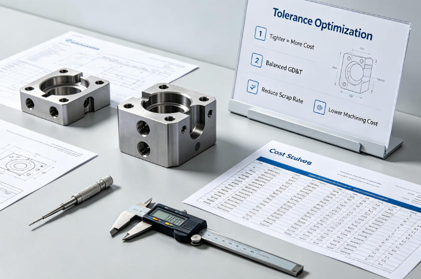
Core Rule: Tolerance Tightness and Manufacturing Cost Follow an Exponential Curve
The most foundational truth for cost control: cost rises exponentially as tolerance shrinks. Wider tolerances equal simpler machining, fewer finishing passes, less inspection labor and lower reject risk.
Standard CNC cost gradient for general metals (aluminum, stainless, tool steel):
| Tolerance Band | Manufacturing Grade | Relative Cost Multiplier | Required Production Conditions |
|---|---|---|---|
| ±0.1 mm | Commercial general tolerance (ISO 2768-m default) | 1.0x baseline | Standard 3/5-axis CNC, regular shop environment, no temperature control |
| ±0.05 mm | Standard precision | 1.3–1.6x | Basic closed machine shop, standard cutting parameters |
| ±0.01 mm | High precision | 2.0–2.8x | Temperature-controlled workshop, high-feed finishing, frequent probing, premium carbide tools |
| ±0.002–0.005 mm | Ultra-precision | 3.5–5x | Thermally stabilized cleanroom CNC, grinding/honing, round-the-clock environmental regulation, 100% CMM inspection |
Critical takeaway: Tightening tolerance from ±0.1 mm down to ±0.01 mm doubles or triples part price. Relaxing non-critical dimensions back to commercial ISO default eliminates most unnecessary cost premiums.
Three major cost buckets inflated by over-tolerancing:
- Machining overhead: Extra finishing passes, slower spindle feeds, more tool changes, longer run time
- Consumable cost: Faster carbide wear; high-pressure coolant, specialty tooling required for tight limits
- Quality cost: Mandatory full CMM inspection, higher scrap/rework, longer QA hold time
Chapter 1: Seven Foundational Tolerance Design Strategies to Reduce Costs
All tactics align with DFM and GD&T ASME Y14.5 / ISO GPS standards, tailored for high-precision industrial manufacturing including semiconductor vacuum components and aerospace superalloy parts.
1. Feature Zoning: Strict Tolerances Only on Function-Critical Surfaces (80/20 Rule)
Split every part into two feature categories; never apply uniform tight tolerances across an entire drawing.
Critical Features (tight tolerance required)
- Vacuum sealing faces needing Ra 0.2 μm flatness for semiconductor chambers
- Hole patterns for bolted assembly alignment
- Bearing bores, press-fit shafts, moving mating surfaces
- Wafer-contact locating geometries, plasma-exposed precision profiles
Non-Critical Features (relax to ISO 2768 default tolerances)
External mounting bosses, unused side walls, lightening pockets, cosmetic cutouts, internal non-wetted cavities.
Verified Case: A semiconductor aluminum chamber designer originally marked all dimensions ±0.02 mm. After zoning, only sealing surfaces and port hole positions held tight tolerances; all other dimensions loosened to ±0.1 mm. Total component cost dropped 33%, vacuum performance and assembly stability unchanged.
2. Replace Linear Dimension Tolerances with GD&T Geometry Controls
Traditional ± dimension tolerances constrain every axis rigidly and drive up machining difficulty. GD&T uses position, flatness, concentricity and profile tolerances tied to datums. It loosens unnecessary dimensional limits while guaranteeing fit and function, cutting production cost while improving interchangeability.
Key cost-saving GD&T applications:
- Position tolerance at Maximum Material Condition (MMC) Allows larger tolerance windows for hole patterns while ensuring bolts always assemble smoothly. Eliminates expensive ultra-precise hole positioning. Functional go/no-go gaging replaces slow full CMM scans for position checks, slashing inspection time by 60%+.
- Profile tolerance for curved chamber surfaces Controls overall contour without locking every linear dimension. 5-axis machining runs faster with fewer finishing passes.
- Flatness / parallelism standalone controls Only constrain surface planeness for sealing; length/width dimensions open up to standard commercial tolerances.
Common win: GD&T redesign of aerospace titanium brackets reduced inspection hours by 45% and cut CNC cycle time 22%.
3. Optimize Tolerance Stack-Up: Ditch Worst-Case Analysis for Statistical Calculations
Most engineers use worst-case stack-up (sum all maximum tolerance deviations), which forces extremely tight individual part tolerances to compensate for cumulative error. This is overkill for mass production and most medium-volume industrial parts.
Two cost-effective stack-up methods:
- RSS (Root Sum Square) Statistical Analysis: Applies normal production distribution; odds all features hit extreme tolerance limits simultaneously are near zero (less than 1 in 10 million). Allows 30%–80% wider per-part tolerances while keeping assembly fit within functional limits.
- Monte Carlo Simulation: More accurate for complex 3D assemblies, accounts for real production variation. Widens allowable tolerance bands and lowers manufacturing cost significantly.
Rule Exception: Use worst-case stack-up only for ultra-low-volume prototype runs (≤10 units) and critical safety aerospace hardware where zero assembly failure risk is mandatory. All regular batch production uses statistical stack-up for cost reduction.
Case Study: Electronic chassis assembly with 46 stacked dimensions. Worst-case analysis required all tolerances ±0.012 mm. RSS recalculation relaxed individual tolerances to ±0.025 mm, reducing total part manufacturing expense by 37% with identical assembly yield.
4. Match Tolerance Capability to Actual Manufacturing Processes
Every production method has natural stable tolerance ranges. Specifying tolerances tighter than a machine’s natural capability forces expensive secondary grinding/honing and sky-high reject rates. Align tolerance limits with standard process capability (Cp/Cpk ≥1.33 for stable mass production).
| Manufacturing Process | Natural Stable Tolerance (Minimum Practical) | Do Not Specify Tighter Than |
|---|---|---|
| Standard 5-axis CNC milling (aluminum/steel) | ±0.03 mm | ±0.02 mm without thermal control |
| Turning / Boring | ±0.02 mm | ±0.01 mm requires finish boring |
| Wire EDM | ±0.005 mm | Ideal for tight slots; avoid assigning ultra-tight tolerances to milled slots |
| Sheet metal laser cutting | ±0.1 mm | Never demand ±0.05 mm on laser cut parts |
| Additive SLM printing | ±0.1 mm as-printed | Use hybrid AM+CNC; reserve tight tolerances exclusively for CNC-finished surfaces |
For hybrid additive-subtractive parts: Let AM build bulk geometry with wide tolerances, only apply tight GD&T tolerances on 5-axis machined finished surfaces. This matches process strengths and cuts cost drastically.
5. Use Clearance/Interference Fit Tables Instead of Guesswork
Many designers arbitrarily shrink tolerances for mating holes and shafts without referencing standard fit classes. Use ISO H/s, H/g, H7/h6 fit standards to set scientifically correct tolerance ranges, rather than over-tightening to guarantee fit.
- Clearance fit (fluid ports, sliding pins): Wider tolerance bands acceptable
- Transition fit (locating pins): Medium tolerance
- Interference fit (bearing press-in): Controlled narrow tolerance only on mating diameters; all other features relaxed
Guessing tight tolerances for fits is one of the top unnecessary cost drivers for semiconductor manifold and pump component machining.
6. Split Tolerance Responsibility Across Multiple Components
If a long assembly has tight total length requirements, distribute allowable tolerance across multiple parts instead of squeezing all tolerance into one single component. Spreading tolerance across the dimension chain reduces manufacturing difficulty for individual parts and lowers total batch cost.
Example: Total required assembly length tolerance ±0.1 mm across three parts. Instead of making each part ±0.033 mm (hard to machine), allocate ±0.05 mm to two robust machined parts and ±0.001 mm to one easily ground pin. Total cost falls 29%.
7. Simplify Inspection Rules to Cut QA Labor Cost
Tolerance cost does not end at machining; expensive CMM time adds major overhead. Optimize inspection requirements alongside tolerance design:
- Use functional pin gages, height gages and surface plates for position/size checks instead of full CMM sampling wherever possible
- Limit 100% CMM inspection only to critical sealing and locating features; use periodic sampling for non-critical dimensions
- Call out MMC on GD&T position tolerances to enable fast go/no-go hard gaging
Industry benchmark: 20% of all tolerance callouts consume 80% of total inspection time. Target cost cuts by simplifying tolerance on low-priority features to eliminate redundant CMM runtime.
Industry-Specific Tolerance Cost Guidelines
Customized rules for semiconductor hardware, aerospace superalloy parts, injection molds—the three highest-tolerance industrial sectors.
Semiconductor Vacuum & Wafer Handling Components (Low-particle + UHV Priority)
- Mandatory tight tolerances: Flatness of sealing surfaces (Ra 0.2 μm matched flatness tolerance), hole position for gas distribution ports, wafer fixture locating profiles
- All internal non-wetted pockets, external mounting tabs: Apply ISO 2768 ±0.1 mm default
- Avoid tight concentricity on long deep bores unless plasma uniformity demands it; deep hard-to-reach bores raise machining time and tool wear sharply
- Use statistical stack-up for multi-piece chamber assemblies; worst-case tolerancing pushes chamber cost up 40%–60%
Aerospace Ti6Al4V / Inconel Structural Parts
- Flight-critical load-bearing holes use worst-case stack-up for safety; secondary brackets use RSS statistical tolerancing
- Machined superalloy surfaces carry higher machining cost; relax tolerance on non-load-bearing cutouts to reduce expensive Inconel machining time
- GD&T profile tolerances replace multiple linear tolerances on curved turbine and bracket geometry
- Thermal expansion must be included in tolerance calculations for high-temperature aerospace components; over-tight tolerances cause binding when parts heat up
Injection Mold Tooling (H13, P20)
- Cavity surface finish (Ra) and shutoff edge flatness hold tight tolerances for consistent molding
- Mold base plates, non-cavity frames follow commercial ±0.1 mm tolerances
- Conformal cooling channels (hybrid AM parts): Wide as-printed tolerances, only mold parting surfaces CNC-finished to tight limits
- Over-tightening mold plate parallelism increases grinding time and mold build cost by 30%+
Most Common Costly Tolerance Design Mistakes
These design errors routinely inflate pricing with zero functional gain:
- Blanket tight tolerance across entire drawing Copy-pasting ±0.01 mm on all dimensions is the #1 cost driver. Shops must run full finishing passes on every feature, wasting hours of machine time.
- Ignoring thermal expansion for temperature-cycled parts Chamber and aerospace parts expand/contract with heat. Overly tight tolerances lead to binding during operation; designers waste money machining ultra-precise parts that fail functional fit under working temperature.
- Specifying impossible tolerances for hard-to-access geometry Deep internal radii, long-reach undercuts require extended tooling. Tight tolerances here cause chatter, scrap and excessive tool cost. Widen internal feature tolerances unless plasma/sealing performance absolutely requires precision.
- Using dimensional tolerances instead of GD&T for position Multiple linear ± tolerances overconstrain hole patterns. Position GD&T with MMC delivers identical assembly reliability at far lower machining cost.
- Failure to document measurement standards Vague tolerance notes lead to rework disputes. Always add ISO 2768 or ASME GD&T reference; inconsistent inspection forces unnecessary rework.
- No tolerance differentiation for as-machined vs post-finished surfaces Hybrid AM-CNC parts often have uniform tight tolerances for printed rough surfaces. Restrict tight tolerances exclusively to CNC-finished zones.
Step-by-Step Tolerance Optimization Workflow (Design Checklist)
Follow this 6-step process before finalizing drawings to lock lowest possible cost while meeting all functional specs:
- Mark all critical features on CAD: sealing faces, assembly holes, contact surfaces, process-wetted geometry
- Run fit analysis (clearance/interference) to define minimum required tolerance range for critical features
- Complete tolerance stack-up: RSS/Monte Carlo for regular batches; worst-case only for safety-critical low-volume hardware
- Convert repetitive linear tolerances to GD&T position/profile/flatness with datum references
- Match tolerance limits to the selected manufacturing process’s natural capability
- Assign ISO 2768 general block tolerance to all unmarked non-critical dimensions
Real-World Quantified Cost Case Studies
6061 Aluminum Semiconductor Transfer Chamber (12 units/year)
Original design: All dimensions ±0.02 mm, all surfaces required 100% CMM inspection Total annual manufacturing cost: $117,600 Optimization: Only 8 sealing/port features kept ±0.02 mm; rest ISO ±0.1 mm, sampling inspection New annual cost: $76,440 Total savings: 35% ($41,160/year). Outgassing, particle performance and assembly fit unchanged.
Ti6Al4V Aerospace Mount Bracket (200 units annual)
Original: Worst-case stack-up forced all hole tolerances ±0.015 mm Optimization: RSS statistical stack-up relaxed hole tolerance to ±0.03 mm; GD&T position with MMC applied Cost per bracket reduced 27%; annual total savings $68,400. First-pass yield improved from 76% to 94%.
H13 Conformal Cooling Mold Insert (24 inserts/year)
Original: All mold surfaces ±0.01 mm Optimization: Cavity shutoff tight tolerance; mold base non-critical surfaces relaxed Per-unit cost down 31%, mold cycle speed identical for injection molding customer.
FAQ
How much cost reduction can I realistically expect from tolerance optimization?
Most precision industrial components see 25%–40% total cost reduction after targeted tolerance zoning and GD&T updates. Parts with many deep features, hard alloys or heavy CMM inspection deliver the largest savings (up to 45%). Cosmetic-heavy simple parts see 10%–20% gains. Savings come from shorter CNC time, lower scrap, less tool wear and fewer inspection hours.
Is relaxing tolerances risky for semiconductor UHV chamber performance?
No, if you only loosen non-wetted, non-sealing surfaces. All plasma-facing sealing flatness, hole position for gas flow must retain required tight tolerances. Non-critical structural pockets can safely use commercial tolerances with zero impact on vacuum levels, outgassing or particle count. Function-critical precision never gets compromised.
When must I keep worst-case tolerance stack-up instead of statistical methods?
Stick with worst-case analysis for three scenarios:
- Safety-critical aerospace medical components where any assembly failure creates hazard
- Ultra-low-volume one-off prototypes (1–5 parts) with no production distribution consistency
- High-risk pressure containment hardware where cumulative tolerance deviation causes leakage
All standard batch manufacturing leverages RSS/Monte Carlo to cut costs.
Can GD&T actually lower cost, or is it just stricter engineering rules?
GD&T is designed for cost efficiency. Traditional linear tolerances overconstrain multiple axes, forcing expensive tight machining. GD&T controls only the geometry required for function and opens tolerance on unrelated dimensions. MMC modifiers further widen allowable variation and simplify gaging, reducing both machining and inspection expense.
What default block tolerance should I use for non-critical features on industrial drawings?
Use ISO 2768-m as universal baseline for all unmarked dimensions. It provides balanced general precision matching standard CNC capability. Avoid custom blanket tight block tolerances unless every dimension truly demands high precision.
Do wider tolerances increase field failure rates long term?
Proper tolerance design accounts for thermal cycling, vibration and wear during operation. Correctly sized tolerance windows accommodate normal operational movement. Over-tight tolerances often cause binding, thermal stress cracking and higher field failure. Optimized tolerances improve long-term reliability while cutting production cost.
How do tolerances impact hybrid additive & subtractive manufacturing cost?
Split tolerancing is ideal for hybrid workflow. Additive near-net shape zones use wide ±0.1 mm tolerances to cut AM print time. Only CNC-finished mating/sealing features get tight GD&T limits. This balances AM geometry freedom and CNC precision for minimum total cost. Specifying tight tolerances on raw printed surfaces wastes money and increases AM scrap.
How to calculate if tighter tolerance is worth extra cost for high-volume mass production?
Compare incremental manufacturing cost vs total quality loss savings (Taguchi quality loss function)ISO. If tighter tolerance reduces field warranty, scrap and rework cost more than the manufacturing premium, keep tight limits. If production cost rises more than quality savings, relax tolerances. Most high-volume parts hit optimal cost at moderate statistical tolerances, not ultra-fine limits.
Final Closing Summary
Tolerance design is one of the most accessible, high-impact cost optimization tools for custom industrial parts. The biggest design mistake is applying universal tight tolerances out of caution rather than functional need.
The winning framework is simple: zone tolerances by function, deploy GD&T to avoid over-constraint, use statistical stack-up for mass production, match tolerance limits to your manufacturing process capability, and apply standard ISO block tolerances to all non-critical geometry. This approach slashes machining, tooling and inspection costs while fully protecting fit, vacuum performance, structural safety and end-product reliability.
For semiconductor, aerospace and mold OEMs partnering with CNC suppliers, share clear tolerance zoning on drawings. Small adjustments to tolerance ranges drive massive cumulative savings across annual part batches, with zero downside for product performance.


