
Published:Zorapid.Ltd
Plastics differ fundamentally from metals during CNC milling. Most polymers have low thermal conductivity, poor heat resistance, low stiffness and layered molecular structures. Three recurring defects ruin plastic parts:
- Melting: Heat accumulates at cutting edges, softens plastic, causes built-up edge (BUE), gummy surfaces and tool clogging.
- Warping: Uneven cutting stress, thermal expansion, moisture absorption and clamping force bend finished parts after machining or days later.
- Edge chipping / fraying: Brittle plastics crack at sharp corners, exit edges and thin walls; glass-filled plastics produce rough fuzzy edges.
These flaws are rarely caused by faulty machines. Defects stem from improper design, wrong cutting tools, incorrect feeds/speeds, bad cooling and unstable clamping. This guide compiles actionable, repeatable solutions sorted by workflow: design optimization, tooling, cutting settings, fixturing, cooling strategies, material pre-treatment and post-machining stress relief. All tips apply to common milled plastics: Acrylic, Delrin (POM), Nylon PA6/PA66, PEEK, ABS, PVC, PP, PC, glass-filled plastics.
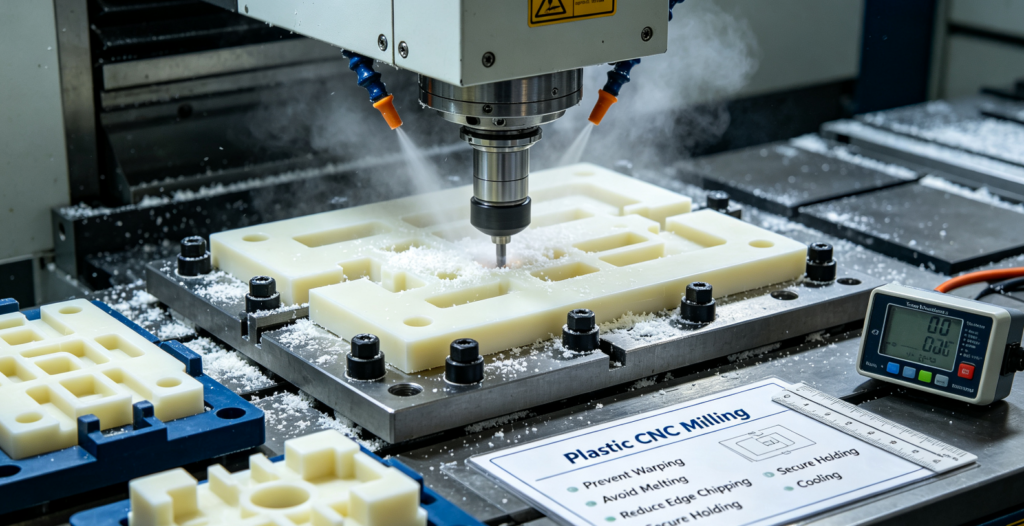
Root Cause Breakdown of Three Major Plastic Milling Defects
Melting
Plastics trap heat at the cutting zone (low heat transfer away from cut). Excess heat melts chips, which stick to cutting flutes, smear workpiece surfaces, and create sticky, uneven machined faces. Slow spindle speed, dull tools, insufficient chip evacuation worsen heat buildup.
Warping
Four primary triggers:
- Machining residual stress: Uneven material removal pulls internal molecular tension; thin sections deform once bulk stock is cut away.
- Thermal stress: Hot cutting zones expand plastic locally; cooling creates uneven contraction.
- Moisture swelling: Nylon, ABS absorb atmospheric water; dimensions shift and bend after machining.
- Over-clamping: Excessive vise pressure crushes thin plastic walls; material springs back after release.
Edge Chipping & Fraying
Brittle plastics (acrylic, PC, PVC) crack when cutting force pushes material outward at exit edges. Glass-reinforced plastics have rigid glass fibers that tear plastic matrix, leaving fuzzy ragged edges. Dull tools apply tearing force instead of clean shearing.
Design for Milling (DFM Rules to Eliminate Defects Upfront)
Design changes deliver the highest defect reduction with zero machine cost increases. All rules apply to all rigid millable plastics.
Wall Thickness Control to Stop Warp & Chipping
| Plastic Type | Minimum Recommended Wall Thickness | Notes |
|---|---|---|
| Acrylic / PC / PVC (brittle) | 1.5 mm minimum; 2 mm preferred | Thin walls under 1 mm chip heavily during through cuts |
| Delrin POM / ABS / PP | 1 mm minimum; 1.2 mm for long spans | Low rigidity causes bowing on tall thin ribs |
| Nylon PA6/PA66 (unfilled) | 1.2 mm minimum | Moisture amplifies warping on thin geometry |
| Glass-filled nylon/PEEK | 1.8 mm minimum | Glass fibers increase brittleness; easy edge breakout |
Rule: Maintain uniform wall thickness across the whole part. Alternating thick/thin sections create uneven material shrinkage and permanent warping. Avoid tall free-standing ribs taller than 6×wall thickness. Add light supporting gussets for long thin ribs.
Edge & Corner Geometry to Prevent Chipping
- Add 0.3–0.8 mm entry/exit chamfers on all through-hole drill exits and open mill edges. Chamfers spread cutting force and eliminate brittle breakout.
- Replace sharp internal 90° corners with radii ≥tool radius. Sharp internal angles concentrate stress and split plastic during milling.
- For acrylic and polycarbonate: Avoid full through cuts on thin perimeters whenever possible; leave thin sacrificial tabs to hold edges intact during machining. Tabs are trimmed manually after milling.
Stress-Relief Design to Reduce Long-Term Warp
- Avoid deep asymmetric pocketing. Balance material removal on opposite sides of the workpiece.
- Do not design large solid thick blocks with deep pockets. Thick plastic retains massive internal molding stress; machine stress-relief slots to release tension before final finishing.
- Limit long cantilever features; unsupported extended plastic sections vibrate during cutting, triggering both chipping and heat melting.
Moisture-Related Design Adjustment
Nylon and cast ABS absorb humidity. If tight dimensional stability is required:
- Specify moisture conditioning of raw blanks before milling
- Avoid overly tight tolerances (±0.02 mm or tighter) on large nylon parts; loosen non-critical tolerances
Tool Selection – The Most Underestimated Fix for Melting & Chipping
Standard metal end mills generate heat and tear plastic. Plastic-dedicated cutters enable clean shearing.
End Mill Types by Plastic Family
- Single-flute high-helix plastic end mills (Top Universal Choice) Large flute spaces evacuate chips instantly, reduce heat buildup to stop melting. Sharp high-shear cutting edges slice plastic rather than push/tear material. Best for: Acrylic, ABS, Delrin, PVC, PP, solid PEEK. Minimizes edge fraying drastically.
- Two-flute upcut / downcut compression end mills Compression tools combine upcut flutes on bottom and downcut flutes on top. They lock workpiece edges down during cutting, eliminating top-layer chipping for laminated plastics, acrylic sheets, PC panels. Ideal for thin plate plastics.
- Solid carbide polished tools mandatory Polished flute surfaces prevent melted plastic chips from sticking (no BUE buildup). Unpolished HSS tools create heavy melting and sticky residue. Never use dull tools; dull edges rub instead of cut and overheat plastic.
Tool Do’s and Don’ts
Use sharp, newly polished carbide cutters for all plastic jobs
Select larger flute volume for thermoplastics prone to melting (PP, ABS)
Avoid multi-flute (4-flute, 6-flute) metal end mills on plastic: small flutes trap chips and overheat material
Never use coated tools with rough coating texture; coatings catch molten plastic
Glass-filled plastics exception: Use fine-grain carbide with smooth TiN coating for abrasion resistance; still stick to 1–2 flute geometry for chip flow. Glass wears uncoated carbide fast.
CNC Feeds & Speeds Tuning to Control Heat (Stop Melting)
Heat control relies on high spindle speed + fast feed rate (high speed, high feed / HSHF). Slow RPM causes tool rubbing and extreme heat. All values below reference solid carbide single-flute tools.
General Universal Plastic Parameter Logic
High RPM to shear plastic; fast feed so the tool cuts through material quickly instead of dwelling and heating one spot. Reduce depth of cut to limit cutting load and heat generation.
| Plastic Grade | Spindle Speed RPM | Feed Rate (mm/min) | Maximum Depth per Pass |
|---|---|---|---|
| Acrylic PMMA | 12,000–24,000 | 1,200–2,400 | ≤1 mm |
| Delrin POM | 10,000–20,000 | 1,500–2,800 | ≤1.2 mm |
| ABS | 12,000–22,000 | 1,600–2,600 | ≤1 mm |
| Nylon PA6/66 | 8,000–16,000 | 1,000–2,000 | ≤1.5 mm |
| PEEK (unfilled/filled) | 6,000–14,000 | 800–1,800 | ≤0.8 mm |
| PVC / PP (soft low-melt) | 15,000–26,000 | 1,800–3,000 | ≤0.7 mm |
| Polycarbonate PC | 10,000–20,000 | 1,100–2,200 | ≤1 mm |
Key rules for all plastics:
- Never run slow RPM with slow feed: rubbing = melting.
- Reduce radial width of cut for deep pockets; step over ≤40% of tool diameter to lower heat.
- Climb milling preferred over conventional milling for plastics. Climb milling produces thinner chips, less friction heat and cleaner edges. Conventional milling pushes material and causes chipping on brittle plastics.
Fixturing Strategy: Prevent Warp from Clamping Stress & Vibration
Most post-machining warping comes from over-clamping or unstable workpiece vibration.
- Light clamping pressure Vise jaws only need enough force to stop workpiece movement. Excessive vise load compresses plastic; the part springs back into warped shape after being unclamped. Use soft aluminum or brass vise jaws to spread clamping pressure evenly and avoid indentations.
- Vacuum fixturing for thin plastic sheets Flat thin acrylic, PC, ABS sheets warp easily under point clamping. Vacuum tables distribute holding force uniformly with zero localized compression. This eliminates clamp-induced bending entirely.
- Sacrificial support boards Machine plastics on top of MDF, HDPE or phenolic backup sheets. The support material stops edge breakout when the cutter exits through the plastic bottom layer, curing bottom-side chipping. Backup boards also damp vibration.
- Avoid clamping only tiny plastic tabs Small contact points concentrate stress; spread clamping across large flat datum surfaces. For complex geometry, use custom low-profile plastic fixtures with large contact areas.
- Anti-vibration setup for tall thin plastic features Add removable support blocks against tall ribs during milling; remove supports after all cuts are complete. Vibration creates repetitive micro-cracks and edge chipping.
Cooling Methods – Critical to Avoid Melting (Plastic Cooling Rules Differ from Metals)
Liquid flood coolant causes two major plastic issues: moisture absorption warping (nylon, ABS) and thermal shock cracking (acrylic, PC). Choose cooling by plastic type.
Compressed Air Cooling (Most Versatile Default for All Plastics)
Dry cold air blast directed straight at the cutting zone. Air removes hot chips rapidly with zero liquid contact. No water absorption, no thermal shock cracking. Best for: Acrylic, PC, Delrin, PEEK, nylon, glass-filled plastics. Use a small air nozzle paired with an air gun; add a cold air vortex tube for extra heat removal on high-RPM jobs.
Mist Coolant (Limited Use Only)
Fine oil mist for hard-to-machine glass-filled PEEK/Nylon. Pure liquid flood coolant is forbidden. Mist delivers minimal lubrication without enough liquid to soak plastic. Shut down mist entirely for nylon to prevent water uptake warping.
Cooling Strictly Forbidden
Full water flood coolant on acrylic (thermal shock cracks), nylon (moisture warp), PP/PVC (swelling and dimensional shift). Cool only with air on these materials.
Chip Evacuation Note
Plastic chips melt if trapped in flutes. Combine high airflow with high-feed machining to eject chips before they melt and adhere to tools.
Pre-Material Treatment & Post-Machining Stress Relief to Stop Long-Term Warp
Many plastics hold internal residual stress from extrusion/injection molding. Stress releases gradually post-machining and warps parts days or weeks later.
Pre-Machining Stress Relief (Annealing Raw Stock)
Anneal plastic blanks before milling to release molding/extrusion stress. Standard annealing cycles:
- Acrylic: Heat 80°C for 3–4 hours, cool down 5°C per hour slowly
- PC: 120°C for 2–4 hours, gradual cooling
- Nylon: 80°C hot water soak then air dry; stabilizes moisture content
- PEEK: 180°C for 2 hours for stress relief
Skip annealing only for low-tolerance non-critical components. High-precision plastic parts require blank annealing before any CNC cuts.
Post-Machining Stabilization
- After milling, lay flat parts on a level plate at room temperature for 12–24 hours before final dimension inspection. Allow thermal contraction to finish fully.
- Nylon parts need controlled humidity storage after machining to prevent ongoing expansion/shrinkage.
- If warping appears after release: Light re-annealing corrects mild distortion. Severe warping comes from bad cutting stress or poor design and cannot be fixed with heat treatment.
Moisture Pre-Conditioning for Hydroscopic Plastics
Nylon and unfilled ABS absorb water from air. For precision work: Condition raw plastic to match end-use environment humidity before machining. Dimensions stabilize and eliminate moisture-driven warping.
Targeted Troubleshooting Table
| Defect | Exact Cause | Fast Remedy |
|---|---|---|
| Surface melting, sticky gummy finish | Slow spindle speed, dull tool, poor chip evacuation | Increase RPM, switch to single-flute polished carbide, add strong air cooling |
| Top edge chipping on acrylic sheets | Downcut force tears top layer | Use compression end mill + sacrificial backup board |
| Bottom edge fraying on through holes | No workpiece support at exit | Machine on HDPE/MDF backup plate |
| Part warps right after unclamping | Over-tight vise clamping | Loosen vise pressure, switch to vacuum fixture |
| Part warps 2–3 days post-machining | Residual molding stress | Anneal raw blanks before milling |
| Glass-filled plastic fuzzy rough edges | Abrasive dull tool, low shear cutting | New polished carbide, higher RPM climb milling |
| Thin ribs bend after machining | Uneven material removal, cutting force stress | Uniform wall thickness, add rib gussets, lower depth of cut |
| Acrylic cracks randomly mid-cut | Liquid coolant thermal shock | Remove all liquid coolant; cool with dry air only |
Material-Specific Quick Guidelines for Common Plastics
Acrylic (PMMA)
- Biggest risks: Thermal shock cracking, brittle chipping, melting
- Rules: Air cooling only, compression end mills for sheets, chamfer all hole exits, anneal blanks, no flood coolant. Climb milling mandatory.
Delrin POM
- Prone to melting and BUE; low tendency to warp
- Use single-flute carbide, high feed/speed, air cooling. Delrin machines clean; chipping is rare if tools stay sharp.
Nylon PA6/PA66
- Primary risks: moisture warp, heat melting
- Pre-condition moisture, air cooling only (no water), thicker minimum walls, anneal to reduce stress.
PEEK (Filled & Unfilled)
- High heat resistance but high cutting force; glass-filled PEEK wears tools fast
- Moderate RPM, shallow cuts, polished carbide tools with TiN coating. Air vortex cooling for heat control.
Polycarbonate PC
- Brittle and sensitive to temperature change; easy chipping
- No liquid coolant, compression tools for flat stock, chamfer edges, slow cooling after annealing.
PVC / PP
- Very low melting point; melts easily with slow cutting
- Max spindle RPM, ultra-fast feeds, light cuts, heavy air blast to eject hot chips. Avoid all liquid cooling.
Glass-Reinforced Plastics (GF Nylon / GF PEEK)
- Glass fibers cause edge fraying and rapid tool wear
- Use smooth coated carbide, high shear single-flute geometry, climb milling, sufficient air cooling. Increase wall thickness to resist fiber breakout.
FAQ
Can flood coolant ever be used for plastic CNC milling?
Almost never. Water-based coolant causes acrylic/PC thermal cracking, nylon moisture swelling warping, and dimensional instability. Only tiny amounts of fine oil mist are allowed for glass-filled high-temperature plastics; dry compressed air remains the universal safe cooling solution.
Why do 4-flute metal end mills produce terrible results on plastic?
Four flutes create narrow flute channels that trap hot plastic chips. Chips melt inside flutes, stick to tools, cause surface smearing. Single-flute cutters have oversized flutes for fast chip evacuation, the key to stopping melting.
How to stop acrylic chipping on hole exit sides reliably?
Machine with a sacrificial HDPE backing board so the drill/end mill cuts into support material instead of breaking out acrylic edges. Adding exit chamfers also disperses exit cutting force.
My plastic part warps after machining, can annealing fix it?
Annealing corrects warping caused by internal molding/extrusion residual stress. Warping from over-clamping, uneven cutting load or bad thin-wall geometry cannot be fixed with heat treatment; you must revise design or fixturing.
What is the simplest adjustment to reduce all three defects (melt, warp, chip) at once?
Switch to sharp single-flute polished carbide tools, adopt climb milling, use dry air cooling, and apply light uniform clamping. These four low-cost changes resolve most common plastic milling defects across nearly all polymer grades.
How to machine thin plastic plates without bending and edge fraying?
Use vacuum table fixturing for even holding force, compression end mills, HDPE backup support, high-RPM high-feed parameters, and air cooling. Avoid mechanical vise clamping on thin plastic panels.
Final Conclusion
Warping, melting and chipping during plastic CNC milling are controllable through layered optimization: design first, then tooling, cutting parameters, fixturing, cooling and stress relief.
- Design uniform wall thickness, add radii/chamfers and sacrificial tabs to eliminate geometry-driven chipping and warp.
- Choose high-shear polished single-flute or compression carbide tools; avoid multi-flute metal cutters that trap heat.
- Run high spindle speed paired with fast feed rates, shallow cuts and climb milling to minimize heat buildup.
- Use light clamping or vacuum fixtures; support all through-cut edges with backup boards. Dry compressed air is the primary cooling method for all plastics.
- Anneal raw plastic blanks and stabilize humidity for hygroscopic materials to eliminate delayed warping caused by residual internal stress.
Glass-filled and brittle plastics require extra attention to tool wear and cutting shear force. When design, tooling and process align, plastic milling achieves smooth edges, consistent dimensions and zero thermal deformation.


