
Published by: Zorapid.Ltd
The biggest headache with aluminum sheet metal parts? Poorly defined tolerances.
You send out a DXF file with no clear specs, then get parts that won’t assemble.
Laser-cut holes shift out of position, bent flanges drift long, and aluminum springback throws bend angles out of spec.
Over-tight tolerances push up cost by 30% for no real benefit. Loose limits lead to batch scrap and delayed shipments.
At Zorapid, we fabricate thousands of 5052 and 6061 aluminum enclosures and brackets every month.
We strictly follow ISO 9013 for laser cutting and ISO 2768-m for CNC press brake bending, the global baseline accepted by North American and European OEMs.
Today we lay out the full, shop-proven tolerance standard: cutting accuracy, hole position, bend dimension, angular deviation and springback control — all calibrated specifically for aluminum alloy sheet.
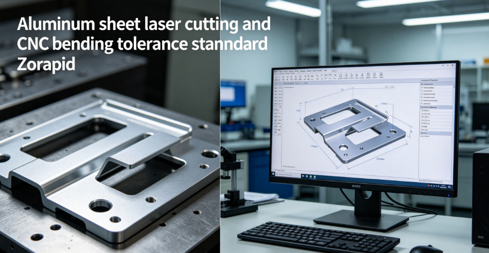
Governing International Standards
No more vague commercial tolerance notes on drawings. Our baseline follows two core norms:
- Dimensional tolerance for fiber laser cutting on aluminum sheet. This controls kerf deviation, edge straightness and hole positioning.
- Default general tolerance for all linear lengths, flange sizes and angular bends unless you specify tighter fine (f) class.
- Supplementary rule: Aluminum has obvious springback. We add material-specific bend compensation outside the base ISO tolerance range.
Material scope covered in this standard:
- 5052-O / H32 general structural aluminum
- 6061-T6 hardened aluminum sheet (0.5mm ~ 12mm thickness)
Key rule we share with all customers:
All non-critical dimensions default to ISO 2768-m. Only mark critical assembly features with reduced tight tolerance to keep cost stable.
Laser Cutting Tolerance for Aluminum Sheet
Fiber laser cutting delivers consistent accuracy, but thickness and part length still create predictable variation.
All values below apply to clean 6061 / 5052 aluminum with stable machine kerf compensation.
Linear Cutting Dimension Tolerance
| Nominal Length Range | Sheet Thickness ≤ 3mm | Sheet Thickness 3–8mm | Sheet Thickness 8–12mm |
|---|---|---|---|
| 0 ~ 100 mm | ±0.08 mm | ±0.12 mm | ±0.15 mm |
| 100 ~ 300 mm | ±0.12 mm | ±0.18 mm | ±0.22 mm |
| 300 ~ 800 mm | ±0.18 mm | ±0.25 mm | ±0.30 mm |
| 800 ~ 1500 mm | ±0.25 mm | ±0.32 mm | ±0.40 mm |
Hole & Slot Position Tolerance (Critical for Enclosure Mounting)
- Standard hole positional tolerance: ±0.15 mm
- Precision grid holes (PCB mounting): Tight class down to ±0.08 mm
- Minimum hole diameter: ≥ 1.2 × sheet thickness to avoid heat distortion on aluminum
Edge Straightness & Kerf Variation
- Cut edge straightness: ≤0.05 mm per 100mm length
- Kerf width controlled within 0.02–0.04mm with automatic laser compensation, no oversized cut gaps on aluminum.
Common mistake: Designers specify ±0.05mm for long aluminum panels over 800mm. This pushes pricing sharply, as thermal expansion makes ultra-tight long-length accuracy extremely hard to hold.
CNC Press Brake Bending Tolerance (Aluminum Springback Included)
Aluminum rebounds far more than steel after bending. Tolerances must account for springback, not just machine accuracy.
We split bending tolerance into four core categories: flange length, bend location, bend angle and flatness after forming.
Flange Linear Dimension
Measured from bend line to the part edge.
| Flange Length | Standard Tolerance (5052 / 6061 Aluminum) |
|---|---|
| < 50 mm | ±0.15 mm |
| 50 ~ 150 mm | ±0.25 mm |
| 150 ~ 400 mm | ±0.35 mm |
Multiple sequential bends create small tolerance stack-up. We limit cumulative deviation below ±0.45mm for multi-fold enclosure shells.
Bend Line Position Tolerance
Distance from edge to bend line: ±0.20mm standard; ±0.12mm for precision folded housings.
Bend Angle Tolerance (Biggest Aluminum Pain Point)
- Standard air bending: ±0.75°
- Precision compensated bending (with springback pre-offset): ±0.4° 6061-T6 hard aluminum has 2–3× more springback than soft 5052. We pre-bend over-angle to cancel rebound before measuring final angle.
Flatness After Forming
Aluminum easily twists during bending.
Flatness tolerance across the formed face: ≤0.25mm per 100mm span for thin sheet below 2mm thickness.
Bend Hole Distortion Rule (DFM Must-Follow)
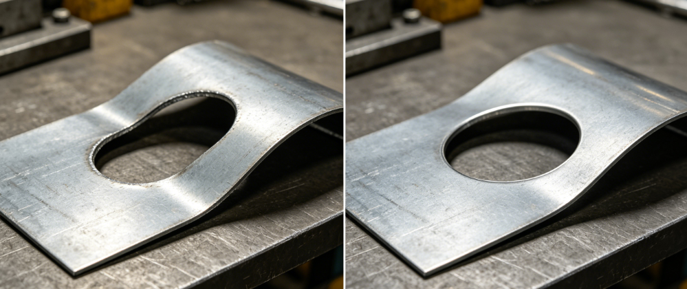
Any hole closer than 2× material thickness to the bend line will stretch out of round.
Tolerance cannot fix this distortion. We add relief slots automatically if holes sit near bend zones.
Combined Process Stack-Up Tolerance
When you chain laser cutting + multiple bends, small errors stack together.
Zorapid’s practical assembly tolerance limit for finished aluminum enclosures:
- Overall outer outline dimension: ±0.40mm
- Two opposite flange parallelism: ≤0.30mm
- Mounting hole grid cumulative position error: ≤0.25mm
If your mating assembly requires tighter alignment, we add secondary CNC milling on critical faces after bending, rather than forcing unrealistic bend tolerances.
Two Tolerance Grades We Offer For Export Aluminum Parts
Grade A: Standard Commercial (Default ISO 2768-m, lowest cost)
Follows all values listed above. Perfect for electrical enclosures, junction boxes, general brackets, powder-coated housings.
First-pass yield >97%, no extra setup charge.
Grade B: Precision Tight Tolerance (Class f)
- Laser cutting accuracy improved by 40%
- Bend angle held within ±0.4° with springback programming
- Hole position tightened to ±0.08mm Best for anodized aluminum instrument casings with tight pin-and-hole assembly. Cost increases roughly 22–28% due to slower machine feed and repeated brake tuning.
We never apply Grade B unless you explicitly call it out on the 2D drawing. This prevents unnecessary cost inflation on regular sheet metal jobs.
Real Zorapid Case Study: 6061 Aluminum Enclosure Batch
Project Info
6061-T6 aluminum control box, 1.5mm sheet, 4 folded sides plus grid mounting holes.
Problem From Poorly Written Tolerances
Original drawing mixed loose long dimensions with ±0.05mm hole position specs without ISO references.
Early samples had bend angle springback and slight hole shift, leading to delayed first article approval.
Revised Tolerance Following Our Standard
- All outline lengths: ISO 2768-m ±0.25~0.35mm
- Mounting holes: Grade B tight tolerance ±0.08mm
- Bend angle with pre-springback compensation held to ±0.4°
- Holes moved 3mm away from bend lines to eliminate stretching
Final Outcome
100% first-pass CMM compliance. The full batch passed EU customer FA inspection without rework.
Top 4 Tolerance Mistakes On Aluminum Sheet Metal
- Ignoring springback on 6061-T6 Designers apply steel bend tolerances to hard aluminum, leading to consistent angular deviation. We pre-program over-bending to offset rebound.
- No separation between cut tolerance and bend tolerance Long panel cutting error plus bend stack-up creates oversized overall dimensions. We split dimension chains to limit cumulative deviation.
- Marking every feature ultra-tight Non-critical cosmetic edges with ±0.05mm specs slow laser speed and increase reject rates without improving assembly fit.
- Holes placed too close to bend lines No tolerance can fix stretched oval holes caused by aluminum forming tension. Only DFM relief slots solve this issue permanently.
Quick Drawing Note Template
Default Tolerance: ISO 9013 Class 1 (Laser Cut) + ISO 2768-m (CNC Bending)
Material: 5052-H32 / 6061-T6 Aluminum Sheet
Critical features marked separately with tight tolerance; bend angles include springback compensation.
This single line eliminates most SQE drawing disputes with US and European buyers.
Why Zorapid Holds Stable Aluminum Cutting & Bending Tolerances
- We calibrate fiber laser kerf daily for aluminum, strictly following ISO 9013 Class 1 cutting accuracy
- Our CNC press brake stores springback offset data for 5052 and 6061 by thickness, minimizing angular deviation
- We split Grade A commercial and Grade B precision tolerances to avoid unnecessary cost hikes
- CMM inspection verifies hole position, flange length and bend angle on every FA first article
- DFM review flags bend-hole interference before cutting starts, eliminating oval hole defects
- Full process traceability for anodized and coated aluminum enclosure batches
Conclusion
Stable aluminum sheet metal accuracy starts with clear, standard-based tolerances, not guesswork.
Use ISO 9013 Class 1 for laser cutting dimensional limits and ISO 2768-m as your baseline bending tolerance. Always account for aluminum springback on CNC press brake work, and avoid over-specifying every dimension to control cost.
At Zorapid, we follow this full tolerance standard for all 5052 and 6061 sheet metal enclosures and brackets. We can mark up your DXF drawings with proper tolerance notes and split critical vs non-critical features during free DFM review.
Send your aluminum sheet part files, and we will lock in achievable, cost-balanced cutting and bending tolerances before production begins.
FAQ
What is the standard laser cutting tolerance for 6061 aluminum sheet?
Under Class 1, short lengths hold ±0.08~0.15mm, and long panels up to 1500mm stay within ±0.25~0.40mm based on thickness.
What bend angle tolerance can we achieve on 6061-T6 aluminum?
Standard bending hits ±0.75°. With programmed springback pre-compensation, we consistently hold ±0.4° for hard tempered 6061 aluminum sheet.
Why do holes near aluminum bends turn oval?
Forming tension stretches the metal close to the bend line. No tolerance adjustment fixes this. The only solution is moving holes at least 2× sheet thickness away or adding relief cutouts.
Is ISO 2768-m the correct baseline for aluminum bending?
Yes. This medium grade is the global commercial sheet metal default accepted by nearly all US and European OEMs. Reserve ISO 2768-f fine grade only for critical assembly features.
How much extra cost comes with tight precision tolerance on aluminum enclosures?
Tight Grade B tolerance raises total cost roughly 22–28% due to slower laser feed, repeated brake tuning and extra inspection time.


