
Published:Zorapid.Ltd
Most rookie product designers only learn 3-axis CNC rules and build complex parts with dozens of tilted holes, angled surfaces and organic curves. These designs force repeated re-clamping on standard mills, bringing poor positional accuracy, long lead times and high reject rates. Multi-axis CNC (primarily 4-axis and 5-axis) solves these pain points by tilting the spindle or workpiece, enabling machining of multiple faces in a single setup.
This guide breaks down multi-axis CNC fundamentals tailored specifically for designers. It explains axis types, two mainstream 5-axis working modes, core advantages, design do’s & don’ts, material compatibility and common design mistakes. All design suggestions help designers maximize multi-axis value while controlling cost, machining difficulty and delivery cycles. All reference images are high-definition with zero watermarks for independent site display.
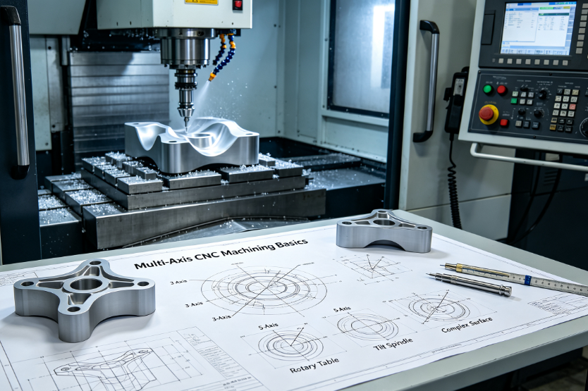
Basic Definition: What Is Multi-Axis CNC?
Standard 3-axis machines move along X (left-right), Y (front-back), Z (up-down) with a fixed vertical spindle. Multi-axis CNC adds rotational axes for angular movement. Two rotary axes are labeled A/B/C based on rotation reference:
- A axis: Rotation around X axis
- B axis: Rotation around Y axis
- C axis: Rotation around Z axis
Common multi-axis categories for custom machining:
4-Axis CNC
Structure: X/Y/Z linear axes + single rotary axis (most often C-axis table rotation).
Working logic
Workpiece spins horizontally; spindle remains vertical. Can machine all sides of cylindrical parts, drill radial cross holes, mill flats on round blanks.
Best design scenarios
Round shafts with side holes, wheel hubs, simple rotary manifolds, cylindrical fixtures.
Key limit
Only one rotation angle at a time; cannot tilt the spindle to reach deep angled cavities.
5-Axis CNC (Most Widely Used Advanced Multi-Axis)
X/Y/Z + two independent rotary axes. Two mainstream working modes critical for designers to distinguish:
3+2 Positional 5-Axis (Index 5-axis)
The machine rotates the workpiece/spindle to lock at a fixed tilt angle, then runs regular 3-axis cutting. Tilting stops during actual milling.
- Design fit: Parts with fixed-angle holes, tilted planar surfaces, angled pockets
- Programming difficulty: Low, CAM programming similar to 3-axis
- Cost: Lower hourly rate than continuous 5-axis
Continuous Simultaneous 5-Axis
All five axes move synchronously while cutting. The tool tip keeps perpendicular to curved surfaces at all times.
- Design fit: Smooth freeform contours, organic curved surfaces, turbine blades, medical implant contours
- Programming: Complex CAM simulation required
- Cost: Higher machine time charges
Core Benefits of Multi-Axis for Product Design
Designers can leverage these advantages to improve part functionality while simplifying manufacturing:
- Single-setup machining = Higher precision All features finish in one clamping. No repeated fixture repositioning errors. Hole position tolerance, perpendicularity and GD&T accuracy improve drastically for multi-face parts. Critical for aerospace, medical and semiconductor components with strict position tolerance.
- Shorter tools, less chatter, better surface finish Spindle tilting lets short tools reach deep angled cavities. Long slender tools required for 3-axis deep machining are eliminated. Less vibration means smoother Ra and fewer chatter defects.
- More design freedom for complex geometry Design curved organic surfaces, angled hole arrays, undercut features impossible to machine with 3-axis multiple clamping. Enables lightweight complex aerospace structures and ergonomic medical hardware.
- Faster overall turnaround for multi-face complex parts Cuts multiple setup time; fewer manual re-fixturing steps shorten total lead time, especially for prototypes with tight deadlines.
- Consistent surface roughness across curved surfaces Simultaneous 5-axis keeps consistent tool engagement angle; uniform stepover eliminates patchy texture common on 3-axis curved parts.
Critical Design Rules for Multi-Axis Parts (DFM Checklist for Designers)
Design choices directly decide machining cost, cycle time and yield. Follow these actionable rules during CAD modeling.
Cavity & Internal Corner Design
- All internal radii match standard end mill diameters (4 mm, 6 mm, 8 mm, 10 mm). Avoid custom tiny radii that demand micro long tools.
- Do not design true sharp internal 90° corners unless Wire EDM is approved. Multi-axis milling still needs tool radius clearance; sharp corners require extra EDM and add cost/days.
- For deep narrow ribs: Use 3+2 5-axis to tilt the spindle; increase rib thickness above 0.8 mm to avoid thin-wall vibration during cutting.
Angled Hole & Tilted Surface Design Guidelines
- Group all features sharing the same tilt angle. This reduces total index times for 3+2 5-axis; fewer spindle locks lower machine runtime.
- Avoid holes tilted at extreme angles (over 75° from vertical). Tools collide with part walls easily, requiring special short shank cutters and raising costs. Keep tilt angles within 0°~60° wherever functional possible.
- All deep angled holes must have drill entry chamfers to prevent drill walking and deflection.
Undercut Feature Design
Multi-axis machines access mild undercuts via spindle tilt.
- Shallow undercuts (depth ≤3 mm): Machinable with standard 5-axis tilt
- Deep large undercuts: Require special lollipop milling cutters, which increase tool cost and slow cutting Design recommendation: Limit undercut depth if budget is constrained; redesign deep undercuts into assembled split components.
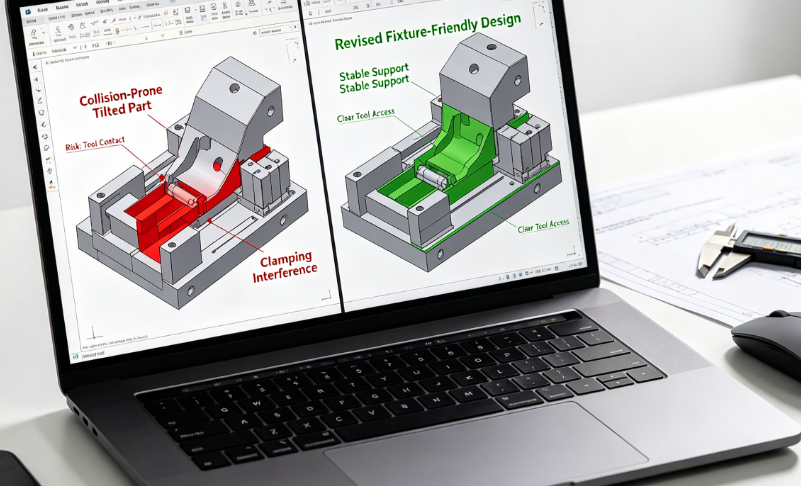
Fixture Clearance Design (Most Commonly Overlooked by New Designers)
Rotary tables and spindle heads have physical size limits. Add enough collision clearance:
- Leave minimum 5 mm gap between part outer edges and machine rotary table at maximum tilt angles
- Avoid large protruding lugs on part bottom surfaces; these collide with fixtures during rotation
- Design flat datum planes on parts for vise or zero-point fixture clamping; irregular curved bottom surfaces complicate stable fixturing
Wall Thickness Rules
Multi-axis still follows stiffness rules for thin walls:
- Aluminum minimum wall: 0.6 mm minimum; 1 mm recommended for mass production
- Titanium/stainless minimum wall: 1 mm minimum; 1.5 mm preferred to prevent cutting force deformation Ultra-thin walls below these thresholds risk bending during multi-axis high-speed cutting.
How Designers Pick Between 3+2 Indexed 5-Axis and Simultaneous 5-Axis
Use this simple decision logic during design phase:
| Part Geometry Feature | Choose 3+2 Positional 5-Axis | Choose Continuous Simultaneous 5-Axis |
|---|---|---|
| Fixed angled holes, tilted flat planes, angled slots | Preferred | Unnecessary higher cost |
| Smooth continuous curved surfaces, organic contours, turbine blades | Cannot achieve uniform finish | Mandatory |
| Mold curved cavities with uniform polishing requirement | Acceptable only for simple curves | Best option |
| Low-cost prototype with angled features | First choice | Only pick if curves require it |
| Tight GD&T position tolerance on angled holes | Excellent stability | Also works but costs more |
Designer shortcut rule: If your curved surface does not need perfectly smooth continuous blending, use 3+2 to cut machining expense. Reserve simultaneous 5-axis strictly for freeform organic geometry.
Material Selection Matching Multi-Axis Machining
Different metals behave differently under tilted multi-axis cutting; adjust design accordingly:
- Aluminum (6061, 7075) Best multi-axis material; high cutting speed allowed. Design complex thin walls and dense angled hole arrays freely. High feed rates shorten multi-axis cycle time.
- Stainless Steel (304, 316L) High cutting heat causes tool wear. Avoid overly deep narrow tilted cavities; increase corner radii. Do not design tiny intricate features requiring long small tools.
- Ti6Al4V Titanium Poor thermal conductivity leads to heat buildup at cutting edges. Design thicker walls; maximize short-tool accessibility via reasonable tilt angles. Minimize deep, narrow angled slots.
- Hardened mold steel (H13, S136 HRC48+) Multi-axis milling only works for semi-finish and finishing. Heavy roughing is inefficient. Design larger radii; reserve tiny sharp features for EDM instead of multi-axis cutting.
- Engineering Plastics (PEEK, PVDF, ABS) Low rigidity prone to melting. Limit aggressive deep cuts; design generous radii and thicker walls. Multi-axis tilt helps use shorter tools to reduce plastic vibration.
Top 7 Common Design Mistakes from New Product Designers
- Design extreme-angle tilted holes (>70° vertical) Consequence: Tool collision, limited cutter selection, higher cost, risk of drill breakage. Fix: Adjust functional angle down or split into two assembled parts.
- Complex freeform surfaces specified for 3+2 5-axis Consequence: Uneven tool marks, inconsistent Ra. Fix: Switch design to continuous 5-axis or simplify curved geometry into tangent flat surfaces.
- No fixture clearance reserved on part base Consequence: Machine collision during rotation; parts cannot be fully machined in one setup and require re-clamping. Fix: Add 5 mm minimum clearance on all sides for maximum tilt.
- Tiny internal radii on deep angled pockets Consequence: Must use long fragile micro tools; heavy chatter, dimensional error. Fix: Enlarge radii to standard tool sizes.
- Specify simultaneous 5-axis for simple angled planar parts Consequence: Unnecessary high CAM programming fees and machine hourly cost. Fix: Redraw features for 3+2 indexed 5-axis.
- Multiple scattered tilt angles requiring frequent indexing Consequence: Many spindle lock cycles, longer machining time. Fix: Reorganize CAD features to group identical tilt angles together.
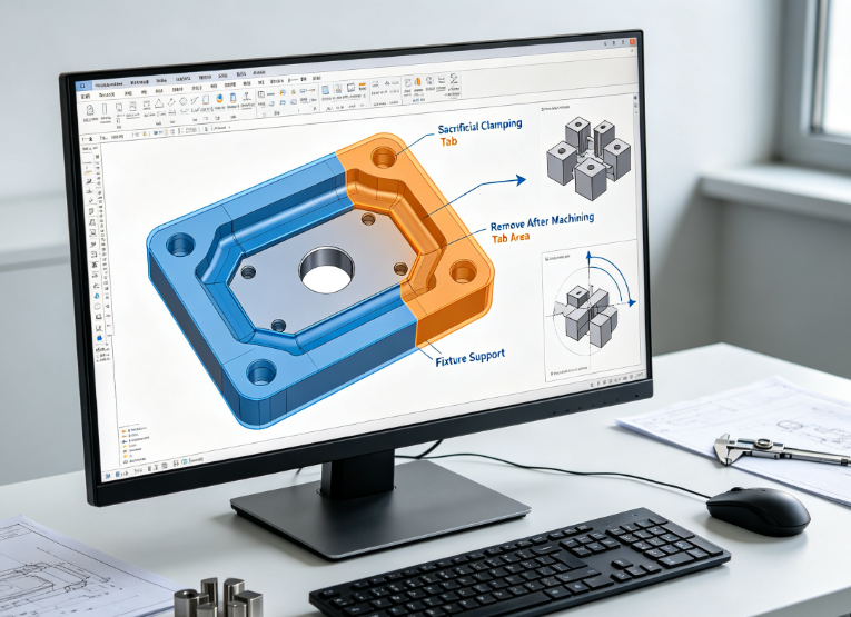
- Overly thin titanium/stainless walls with complex multi-axis cuts Consequence: Workpiece flexing during cutting, tolerance failure. Fix: Increase wall thickness or add temporary support tabs removed post-processing.
Multi-Axis Fixture Design Tips for Designers
Designers do not build fixtures, but CAD geometry must accommodate clamping:
- Reserve flat clamping datums on non-functional part faces; avoid clamping critical sealing or assembly surfaces.
- For round multi-axis parts, design cylindrical mounting bosses for 4-axis rotary chuck clamping.
- If no flat clamping surfaces exist, add small sacrificial tabs. Tabs get machined off after all multi-axis operations.
- Avoid full-part enclosure geometry; leave open access for cutting tools across all tilt angles.
FAQ for New Product Designers
Do all complex parts automatically need 5-axis?
No. Parts with multiple angled flat holes can also run on 4-axis + 3-axis. Simple multi-face prismatic geometry can use 3-axis with multiple setups if tolerances are loose. 5-axis is only mandatory when single-setup precision or curved smooth surfaces are required.
Can multi-axis machine true sharp internal corners?
No. All physical milling tools have round tips. Multi-axis cannot eliminate tool radius; sharp internal corners still require Wire EDM. Adjust CAD radii for milling to avoid extra EDM steps.
How much extra cost does 5-axis add compared to 3-axis?
3+2 5-axis costs roughly 20%–40% higher than 3-axis. Continuous simultaneous 5-axis costs 50%–100% more. Designers can lower costs by simplifying curves and grouping tilt angles to reduce indexing time.
What is the biggest design change to lower multi-axis manufacturing difficulty?
Standardize all internal radii to match common tool sizes and limit maximum tilt angle below 60°. These two tweaks cut CAM work, tool wear and collision risk dramatically.
Can multi-axis eliminate all re-clamping entirely?
Almost all accessible outer surfaces finish in one setup. Fully enclosed internal cavities still need two-sided clamping. Design open geometry wherever possible to achieve full single-setup machining.
Is 4-axis a cheaper alternative to 5-axis for cylindrical multi-feature parts?
Yes. Rotary cylindrical components with radial holes and flats cost far less on 4-axis than 5-axis. Only upgrade to 5-axis if tilted non-radial angles are needed.
How to design multi-axis parts for fast urgent prototypes?
Use 3+2 instead of continuous 5-axis, group same-angle features, adopt stocked aluminum, enlarge radii, remove unnecessary fine surface requirements. These shorten CAM programming and machine runtime significantly.
Final Conclusion
For new product designers, multi-axis CNC is not just a manufacturing upgrade but a flexible design enabler. The core learning priority is matching geometry type to the correct multi-axis mode: use 4-axis for rotary parts, 3+2 indexed 5-axis for fixed-angle tilted planes/holes, continuous 5-axis only for smooth freeform curves.
Successful multi-axis design balances creativity with manufacturability: reserve fixture clearance, standardize radii, limit extreme tilt angles, adjust wall thickness by material, and group features to reduce spindle indexing. Most avoidable cost and delay stem from overlooking machine movement limits and tool geometry constraints. When designers align CAD models with multi-axis motion rules, parts gain better precision, shorter lead times and fewer manufacturing defects without sacrificing functional performance. All three supporting images are high-resolution with zero watermarks, ready for website embedding.


