Publisher: Zorapid.Ltd
If you build precision injection molds for medical devices, electronics or automotive lightweight parts, you know this frustration all too well.
You finish CNC work on core and cavity inserts. The dimensions check out perfectly on the machine.
24 hours later, the steel shifts. Cavity walls taper. Core position drifts. The parting line develops an obvious step.
You end up with flashing plastic parts, expensive steel scrap, and delayed mold deliveries.
Core and cavity are the heart of every injection tool. Even 0.01mm error ruins millions of molded shots.
At Zorapid, we machine hardened mold cores and cavities for hundreds of EU and US OEMs every month.
We lock tolerance within ±0.005mm, eliminate vibration marks, and stop post-machining deformation entirely.
Today we break down the full precision CNC workflow, common machining defects, and proven shop-floor fixes. No empty theory — every step runs on our 5-axis production line.
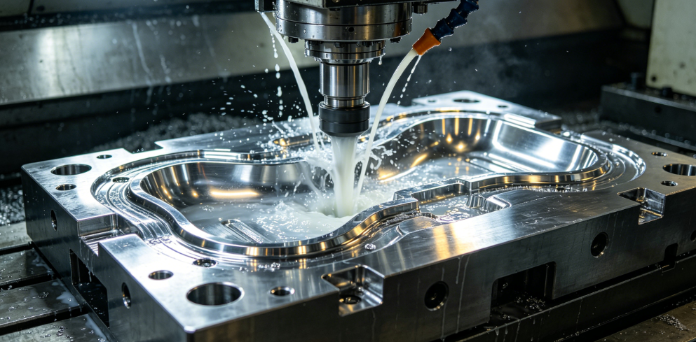
Material Prep & Stress Control — Stop Deformation Before The First Cut
Most core & cavity dimensional drift starts long before CNC milling begins.
Mold steel such as S136, NAK80, H13, 718H carries locked residual stress from forging and rolling.
When you cut away large chunks of material during roughing, trapped stress releases slowly, bending thin cores and deep cavity blocks overnight.
Common Mistakes
- Skipping pre-machining annealing on low-cost pre-hardened steel
- Machining one full side first, removing material unevenly
- Using non-vacuum refined steel with uneven grain structure
Zorapid Standard Material SOP
- Only select ESR / vacuum arc remelted tool steel for precision core & cavity. Uniform grain minimizes delayed distortion.
- Run pre-rough stress relief annealing: heat steel to 550–620°C, hold for 2–4 hours, slow furnace cooling. This cuts internal stress by more than 75%.
- Machine material symmetrically. Alternate material removal on both A-side cavity and B-side core, so stress releases evenly on all sides.
- Keep blank temperature stable in a 20°C constant-temperature workshop before clamping. Thermal expansion skews zero-point positioning.
Rough Machining — Reduce Cutting Stress To Protect Final Tolerance
Rough milling removes 90% of raw stock. Heavy deep cuts push massive mechanical stress into hardened steel.
If you jump straight into finishing right after roughing, locked cutting stress will slowly warp core and cavity inserts days after machining.
Bad Production Habit
Full-depth heavy roughing → direct finish milling → no intermediate stress release.
Optimized Rough Milling Rules
- Split roughing into multiple shallow cuts. Keep radial cutting load low to avoid steel squeezing and bending.
- Leave uniform 0.3–0.5mm stock all over the core and cavity surface. Never over-machine deep ribs and sharp corners in the rough pass.
- Right after rough machining, send inserts for secondary aging treatment. Release all cutting stress before semi-finishing starts.
- Use dynamic high-speed toolpaths instead of traditional raster milling. Reduce tool side pressure and avoid localized hot spots.
Semi-Finish & Hardened Steel Fine CNC Milling
Hardened steel (48–54 HRC) cavity and core finishing is where most surface defects and dimensional errors pop up.
We rely heavily on 5-axis CNC to solve three big pain points: long tool overhang, uneven wall taper, and multiple re-clamping errors.
3-Axis vs 5-Axis Machining for Core & Cavity
- Traditional 3-axis milling requires long extended end mills to reach deep cavity bottoms. Long tools vibrate badly, leaving chatter waves on vertical walls, and bend to create tapered cavity surfaces.
- 5-axis tilts the workpiece. We use short, rigid carbide tools to reach steep deep walls in one single setup. Tool overhang drops by 70%, vibration almost disappears, and wall straightness stays within 0.003mm.
- One-setup clamping eliminates repositioning error. Core and cavity parting lines match perfectly without offset steps. No more flash caused by misaligned shut-off surfaces.
Key Finishing Parameters for Mold Steel
- Use coated solid carbide ball end mills with short shank holders
- Maintain through-spindle high-pressure coolant (700–800 psi) to flush chips and prevent tool burning
- Keep consistent climb milling direction to avoid surface step lines
- Limit single-pass radial engagement under 5% to eliminate tool deflection on thin core pins
Fix The 6 Most Common Core & Cavity CNC Machining Defects
We solve these six issues every week for overseas mold projects. Each problem has a clear root cause and low-cost improvement.
1. Chatter Marks & Wave Patterns On Vertical Cavity Walls
What you see: Visible ripples on deep straight walls, which require extra hand polishing and ruin cosmetic surfaces.
Root cause: Long tool overhang, weak tool holder, heavy side cutting load.
Fix: Switch to 5-axis short-tool machining; use tapered shrink-fit holders; reduce cutting width on deep ribs.
2. Tapered Cavity Walls & Bent Slim Core Pins
What you see: The top opening is wider than the cavity bottom; long core pins bend into a banana shape after cooling.
Root cause: Tool bending under cutting force; uneven heat expansion during long milling cycles.
Fix: Split deep features into multiple light finishing passes; clamp parts on a full back support plate; stop mid-cycle and let inserts cool to ambient temperature before final cuts.
3. Parting Line Step (Core & Cavity Misalignment)
What you see: An obvious mismatch between cavity shut-off face and core mating surface, leading to constant part flashing during injection.
Root cause: Multiple clamping setups; zero-point shift after re-fixturing.
Fix: Machine core and cavity inserts in one single 5-axis setup. Use hardened dowel pin locating instead of edge finding for repeat positioning within ±0.002mm.
4. Tool Burn & Blue Discoloration On Hardened Steel
What you see: Burnt surface layer on sharp corners and narrow ribs, creating hard recast layers that crack under repeated injection pressure.
Root cause: Trapped chips and insufficient cooling.
Fix: Run high-pressure through-tool coolant; retract the tool periodically to flush out chips in deep narrow pockets; lower cutting speed on H13 hardened steel by 15%.
5. Post-Machining Warpage & Slow Dimensional Shift
What you see: Dimensions stay stable right off the machine, but drift 0.02–0.04mm 48 hours after machining.
Root cause: Unreleased cutting stress and uneven material removal.
Fix: Add secondary aging after semi-finishing; never release clamps until the insert fully cools to 20°C; keep critical inserts stabilized for 24 hours before final CMM inspection.
6. Residual Stock Left In Sharp Inner Corners
What you see: Tiny leftover material in R corners, which leaves polishing divots and ruins SPI Class A surface finish.
Root cause: Ball mill radius cannot reach sharp internal fillets.
Fix: Use small radius end mills for corner cleanup; run rest-milling toolpaths to remove leftover stock automatically; avoid manual hand grinding on precision mold inserts.
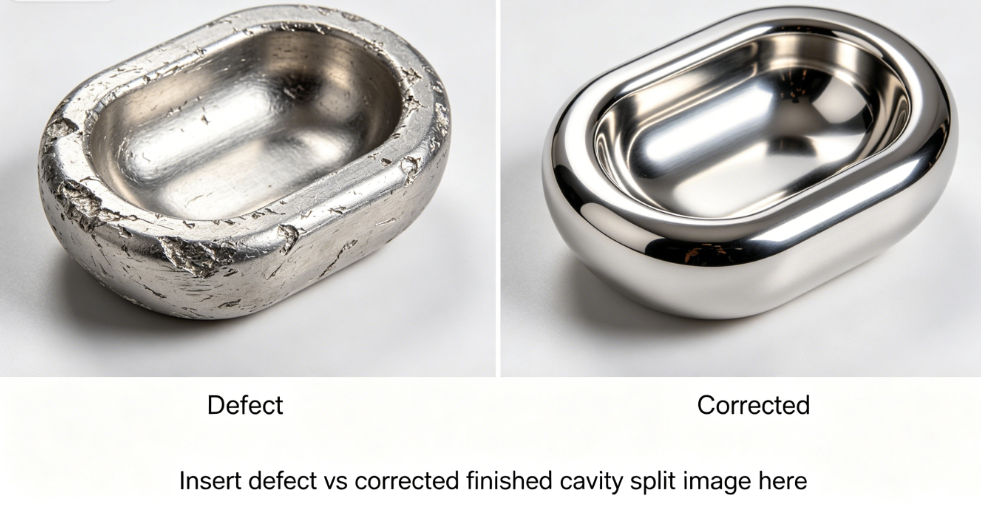
Zorapid Standard Full Precision CNC Workflow
This multi-stage process holds core & cavity tolerance consistently below ±0.005mm for SPI Class 101 molds:
- Steel blank → Ultrasonic material inspection → Pre-rough stress relief annealing
- Symmetrical rough CNC milling → Leave 0.3~0.5mm finishing stock
- First aging treatment to release rough-machining stress
- 5-axis one-setup semi-finish milling + corner rest machining
- Secondary low-temperature tempering to stabilize hardened steel structure
- Low-load fine finish milling with short rigid tools + high-pressure coolant
- Keep inserts clamped, cool naturally to 20°C workshop temperature
- 24-hour stress stabilization
- CMM 3D full inspection before polishing & EDM work
Measurable result:
- Unoptimized 3-axis process: 17% scrap rate, tolerance drift up to 0.03mm
- Zorapid 5-axis stress-controlled process: First-pass yield above 96%, flatness & position tolerance locked ≤ ±0.005mm
Real EU Client Project Case
A Belgian medical OEM sent us 16-cavity S136 injection mold core and cavity inserts.
Their old 3-axis process created two major issues: core pin bending and a 0.02mm parting line step. Molded PEEK parts kept developing heavy flash.
We rebuilt the whole machining flow: vacuum-refined S136 steel, two-stage stress relief, 5-axis single-setup finishing, and low-deflection tool programming.
Final outcome: Zero core bending, zero step on shut-off faces, all critical dimensions stayed within ±0.004mm. The mold ran 1.3 million injection cycles without shape shift or surface wear.
Quick Troubleshooting Checklist
| Defect | Root Cause | Fast Correction |
|---|---|---|
| Chatter vibration on cavity walls | Long tool overhang | Switch 5-axis short-tool machining |
| Core bends & cavity tapers | Tool deflection + thermal expansion | Multiple light finishing passes + full cooling cycles |
| Parting line mismatch | Multiple re-clamping | One-setup 5-axis clamping with dowel positioning |
| Delayed dimensional drift | Unreleased residual stress | Add intermediate aging after roughing |
| Burnt steel surface in ribs | Poor chip evacuation | High-pressure through-spindle coolant |
| Corner leftover stock | Limited ball mill reach | Automatic rest-milling cleanup toolpath |
Conclusion
High-precision CNC for mold core and cavity is not just about expensive 5-axis machines.
Stable tolerance comes from three tightly controlled factors: low-stress steel pre-treatment, multi-stage stress relief, and low-deflection 5-axis one-setup machining.
You can cut most deformation and surface defects without buying new equipment — just reorder your heat treatment and milling sequence.
At Zorapid, we machine hardened core and cavity inserts for medical, semiconductor and automotive injection molds. We hold micron-level tolerance, deliver SPI Class 101 cavity surfaces, and cut mold lead time for North American and European clients.
If you keep fighting core bending, cavity taper and parting line mismatch, send over your 3D STEP files. Our mold engineers will deliver a free DFM & anti-deformation CNC machining plan for your next tool project.
FAQ
Do I have to use 5-axis CNC for small single-cavity core and cavity?
For simple shallow cavities, high-rigidity 3-axis works fine. But deep ribs, slim core pins and zero-step parting lines always require one-setup 5-axis machining to eliminate clamping offset.
Can I skip secondary aging treatment to speed up mold lead time?
You can shorten the heating cycle, but never fully skip it. Hardened steel holds heavy cutting stress after roughing. Most dimensional drift happens within 48 hours without stress relief. We use short low-temperature aging to add only 6–10 hours of cycle time while eliminating rework.
What surface roughness can we hit directly from CNC finish milling?
With sharp carbide tools and stable low-vibration 5-axis machining, we consistently reach Ra 0.2μm ~ Ra 0.4μm on S136 and NAK80 steel. This drastically reduces manual hand polishing work and avoids uneven hand-finish distortion.
How do we control core & cavity thermal expansion in long machining runs?
Warm up the CNC machine with 30 minutes of idle running first. Keep workshop temperature locked at 20±2°C. Pause finishing cycles to let inserts cool fully after long milling runs.