Publisher: Zorapid.Ltd
If you design sheet metal enclosures, brackets or structural panels, you have faced this frustrating problem.
Your CAD file looks perfect. You send it out for laser cutting and press brake bending.
Then the quote jumps far higher than your budget.
Holes stretch into ovals during bending. Corners tear apart. Short flanges slip out of the bending die.
You end up paying for rework, high scrap rates, extra tool changes, and repeated setup time.
Nearly 70% of sheet metal cost waste comes from bad design choices made long before the first laser cut.
DFM (Design for Manufacturability) fixes this entirely.
At Zorapid, we run free DFM reviews for hundreds of EU and US OEM sheet metal projects every month.
We consistently cut laser cutting and bending cost by 18–25% without changing part function or assembly performance.
Today we break down 10 actionable DFM rules focused strictly on cutting cost in laser cutting and press brake bending. Every rule comes straight from our production floor data.
Enforce Minimum Hole-to-Bend & Hole-to-Edge Clearance
What goes wrong in bad design
Engineers often place holes just a few millimeters away from bend lines.
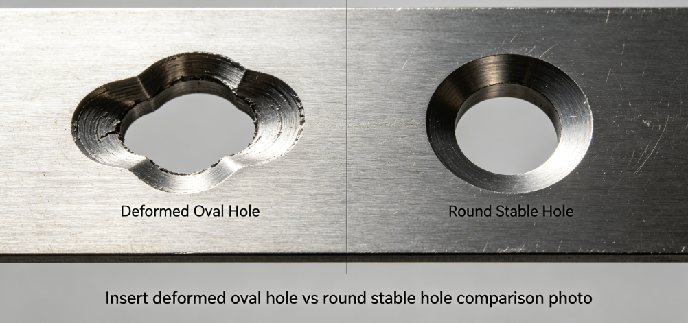
When the press brake folds the sheet, tensile force stretches the round hole into an oval shape.
Fasteners no longer fit, and the whole part gets scrapped immediately.
Holes too close to the outer edge also tear during laser cutting or punching.
Hard DFM Standard (t = sheet thickness)
- Hole edge to bend line: ≥ 3 × t
- Hole edge to outer part edge: ≥ 2 × t
- For stainless steel, expand this gap to 3.5 × t to resist material stretching.
Cost Impact
Moving holes a few millimeters in CAD costs you nothing.
This simple edit cuts bending-related scrap by 12–16% on multi-hole panels.
If you absolutely must keep a hole near the bend, cut the hole after bending instead of before forming.
Add Bend Relief Notches to Stop Corner Tearing
Common fabrication headache
Where two flanges intersect at a right angle, bending pulls metal in two opposite directions.
Without a small relief cutout, the sharp corner splits wide open during forming.
Fabricators cannot repair these cracks; the part gets thrown away.
Zorapid Standard Relief Dimension
- Notch width = material thickness (t)
- Notch length extends 1.5 × t past the bend tangent line
- Never leave solid sharp corners at bend intersections.
Quick Cost Win
Bend relief only adds a short laser cut, with zero extra cutting time.
We eliminate nearly 100% of corner cracking by adding these small notches in the flat pattern.
Standardize Bend Radius & Avoid Mixed Radii
Every time the bend radius changes, the press brake operator has to stop production and swap out tooling.
Tool change kills production speed and adds labor cost.
Non-Negotiable DFM Rule
- Use inner bend radius R = t for all mild steel across the entire part.
- Stainless steel: R = 1.5 × t to prevent cracking.
- Keep ONE single radius value for every bend on the same component.
Measurable Savings
Uniform bend radii eliminate tool swapping.
Press brake cycle time drops by 20–25%, and labor cost per part goes down sharply.
Sharp zero-radius bends are never allowed — they always crack hard sheet metal.
Never Design Flanges Shorter Than The Minimum Bend Height
A tiny short flange cannot be gripped by the press brake die.
The metal slips sideways, creating skewed bends and inconsistent angles.
Operators cannot form these small tabs reliably, which forces secondary hand trimming.
Minimum Flange Height Formula
Minimum flange length h ≥ Bend Radius (R) + 2 × sheet thickness (t)
Example: t=1.5mm, R=1.5mm → minimum flange height = 4.5mm.
Design Fix
Shorten adjacent features or extend the flange slightly to hit the minimum length.
You will completely eliminate unstable bending and secondary grinding work.
Stick to Standard Hole Sizes — No Odd Custom Diameters
Custom decimal hole sizes force the shop to order special punch tools or run slow laser piercing cycles.
Standard drill and punch sizes run fast with existing tooling, which keeps cutting cost low.
DFM Best Practice
Only use standard metric sizes: 3mm, 4mm, 5mm, 6mm, 8mm, 10mm.
Avoid random sizes such as 5.2mm or 7.7mm unless strictly required for assembly.
Minimum hole diameter must be ≥ sheet thickness to avoid laser burn and pinhole defects.
Simplify Notches & Internal Corners for Faster Laser Cutting
Sharp zero-radius internal corners create two expensive problems:
- The laser beam leaves burn marks and stress cracks at sharp points.
- The machine slows down drastically to make tight sharp turns, raising cutting runtime.
Low-Cost Design Change
Add a small minimum radius (R0.5 ~ R1) to all internal cut corners.
The laser runs at full continuous speed, cutting machine time down by nearly 15% on complex cutouts.
Narrow thin notches (width less than 1.5×t) should also be widened to avoid narrow metal slugs getting stuck during cutting.
Control Springback to Reduce Re-Bending Labor
All sheet metal springs back after bending. Aluminum and stainless steel have far higher springback than cold rolled steel.
If you ignore this material property, operators have to repeatedly over-bend and re-adjust angles, wasting machine hours.
DFM Design Control
- Keep bend direction consistent on the same side whenever possible.
- Avoid deep narrow bends that amplify material rebound.
- Relax angle tolerance on non-mating flanges from ±0.5° up to ±1.5°. Every re-bend adds cost; good DFM minimizes trial-and-error on the press brake.
Reduce Setup — Keep Bend Directions Unified
Each time you flip the part to bend upward then downward, the fabricator has to re-clamp and re-align the blank.
Multiple setups multiply labor cost and increase dimensional variation.
Cost-Saving Design Tip
Group all bends to the same side in your flat pattern layout.
Cut setup count from 3 or 4 runs down to just 1 or 2 clamping cycles.
On high-volume batches, this slashes bending labor cost significantly.
Limit Tight Tolerances Only On Critical Mating Surfaces
This is the most overlooked cost waste in sheet metal design.
Engineers often apply tight ±0.05mm tolerances across the entire part, even on cosmetic non-assembly panels.
Tight tolerances require slow low-speed cutting, repeated inspection, and extra manual correction.
DFM Tolerance Rule
- Keep loose standard tolerance (±0.15 ~ ±0.25mm) on all non-mating edges, cutouts and flanges.
- Only apply micron-level tight tolerance to bolt holes, locating slots and mating shut-off faces. This single adjustment can lower total part cost by 10% with zero impact on part function.
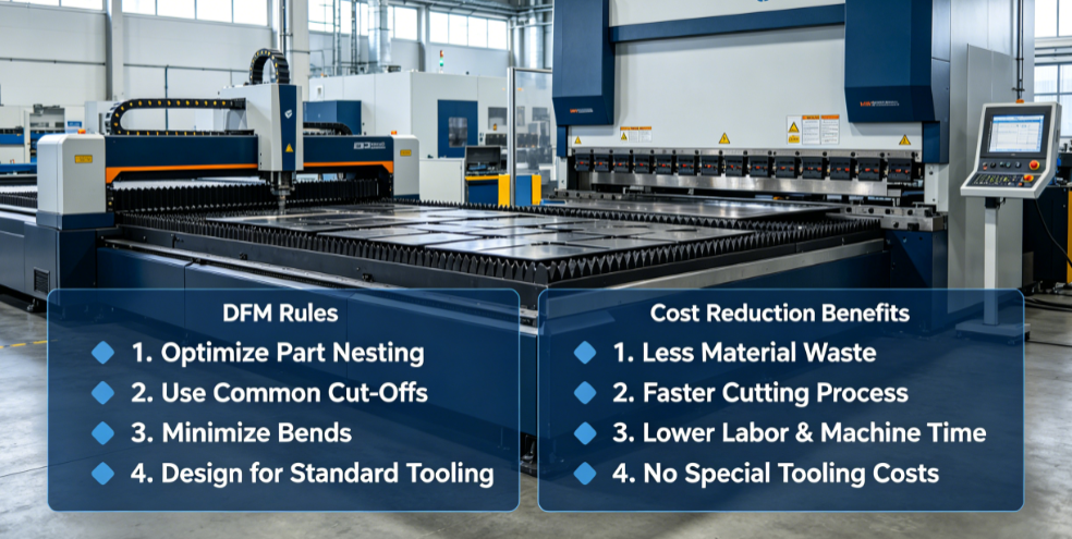
Optimize Flat Pattern Nesting to Slash Material Waste
Laser cutting cost depends heavily on how many parts fit onto one raw steel sheet.
Poor CAD nesting wastes 15–22% of raw material, which makes up the largest portion of your total expense.
Zorapid Nesting DFM Guide
- Rotate small parts to fill empty gaps inside large cutouts (nest parts inside leftover sheet space).
- Align part edges parallel to the sheet grain to avoid bending cracking AND improve packing density.
- Combine multiple part numbers on one sheet for small-batch prototype orders.
Real Cost Data
After re-nesting our client’s panel layout, we dropped material waste from 17% down to 4%.
Material cost alone fell by more than 13% for the full production batch.
Full Zorapid DFM Workflow For Low-Cost Cutting & Bending
Follow this sequence before releasing your drawing for quotation:
- Standardize material to common sheet gauges (1.0mm, 1.5mm, 2.0mm; avoid rare custom thickness)
- Enforce hole-to-bend / hole-to-edge clearance and add all bend relief notches
- Lock one unified bend radius and eliminate mixed-radius tool changes
- Extend all short flanges to meet minimum bend height
- Round all sharp internal corners to speed up laser cutting
- Restrict tight tolerances only to critical assembly features
- Unify bend directions to minimize press brake re-clamping setups
- Re-arrange flat patterns for maximum sheet nesting density
- Run a free Zorapid pre-production DFM check before sending files to fabrication
Measurable Outcome
- Original non-optimized design: 23% scrap + long machine runtime
- Post-DFM revision: Scrap below 3%, cutting & bending total cost reduced by 21%
Real EU Client Case Study (Stainless Steel Equipment Housing)
A Dutch industrial equipment OEM sent us 1.2mm 304 stainless steel enclosure panels.
The original CAD file had three costly DFM mistakes:
- Multiple holes placed too close to bend lines, creating oval deformed holes
- Missing bend reliefs leading to 18% corner crack scrap
- Mixed bend radii forcing 4 press brake tool changes per panel
We revised the flat pattern strictly following our DFM rules: repositioned holes, added corner relief notches, standardized R1.8 bend radii, and re-nested the sheet layout.
Final result:
Zero bending deformation, scrap rate dropped below 2%, total part cost cut by 22%.
The lead time also shortened by one full shift thanks to fewer tool changes and faster laser cutting.
Quick Troubleshooting & Cost-Saving Checklist
| Fabrication Problem | Root DFM Error | Fast CAD Fix |
|---|---|---|
| Round holes turn oval after bending | Holes too close to bend lines | Keep gap ≥3× sheet thickness |
| Corner splits & cracking | No bend relief notches | Add small cutouts at bend intersections |
| Slow press brake production | Multiple different bend radii | Use only one R value for all bends |
| Flanges bend crooked & slip | Flange height too short | Extend flange to meet h ≥ R+2t |
| High laser cutting runtime | Sharp zero-radius inner corners | Add minimum R0.5 corner radii |
| Massive raw material waste | Poor flat pattern nesting | Pack small parts into sheet empty space |
| High inspection & rework cost | Overly strict full-part tolerances | Tight tolerance only on mating features |
Conclusion
Nearly all extra cost in laser cutting and press brake bending comes from small design oversights, not machine capacity or material price.
You do not need to downgrade material or reduce part quality to save money.
Just apply these 10 DFM rules during the CAD design phase.
Every relief notch, every standardized bend radius, and every properly spaced hole directly cuts scrap, labor and machine runtime.
At Zorapid, we provide free DFM design reviews for all sheet metal projects for automotive, medical, semiconductor and industrial equipment clients across Europe and North America.
We optimize flat patterns, fix bending defects, and bring your cutting & bending cost down while holding consistent dimensional accuracy.
Send your STEP or DXF flat pattern files, and our engineering team will deliver a revised low-cost DFM version with full cost breakdown — no obligation required.
FAQ
How much total cost can DFM optimization save on sheet metal parts?
On most standard brackets and panels, well-executed DFM cuts total fabrication cost by 18–25%. The biggest savings come from lower scrap, fewer tool changes, reduced re-bending labor and better sheet nesting.
Can I skip bend relief for small prototype runs?
You might get away with it for 2–3 test pieces. In small batches, corner cracking still creates rework. It takes only 10 seconds to draw a relief notch in CAD, so we always add it regardless of order quantity.
Is springback only a problem for stainless steel sheet?
Aluminum rebounds the most, followed by stainless steel. Mild cold rolled steel still has small springback. Good DFM unifies bend directions and relaxes non-critical angle tolerance to avoid repeated forming corrections.
Does rounding internal corners raise laser cutting cost?
No. Sharp corners force the laser to slow down and make sharp stops. Adding small radii lets the machine run continuously at full speed, lowering cutting time and burn defects at the same time.