
Published:Zorapid.Ltd
You write a clear Ra value on your drawing.
The first sample hits spec perfectly.
Then the next batch comes out too rough, with uneven tool marks and chatter waves.
This inconsistency costs thousands: rework, extra finishing passes, scrapped parts and delayed shipments.
Most CNC workshops set surface finish by guesswork instead of following fixed Ra control standards.
Ra (roughness average) is not just a cosmetic number.
It decides seal performance, friction, wear resistance, anodizing quality and assembly fit.
Over-specify Ra and you double machining time. Under-control it, and whole batches fail inspection.
At Zorapid’s precision milling workshop, we lock surface roughness strictly to ISO & ASME standards.
We hold stable Ra values from the first piece to the last piece of a production run.
Today we break down the complete CNC milling Ra control standard, with actionable settings you can copy directly into your CAM program.
Why Ra Consistency Matters for CNC Milled Components
Ra measures the average height of peaks and valleys on the machined surface.
Even small shifts will ruin part functionality:
- Ra above 1.6 µm on an O-ring sealing face leads to air leakage
- Chatter-induced rough surfaces create stress cracks on aerospace structural parts
- Uneven texture causes blotchy anodizing on aluminum cosmetic housings
- Too fine a Ra on mating surfaces can lead to oil starvation and premature wear
The biggest mistake overseas clients make: applying the same ultra-tight Ra requirement to every surface of one part.
Internal blind pockets do not need Ra 0.8 µm. Only sealing and contact faces require fine finishes.
Smart Ra grading cuts total machining cost by 25–35% without sacrificing performance.
Global Ra Standards: ISO 4287 & ASME B46.1 for CNC Milling
Two global rules govern all our milling jobs for EU and US customers:
- ISO 4287 (Europe, Asia) Defines Ra arithmetic average roughness, with N-grade classification for technical drawings.
- ASME B46.1 (North America) Uses µm and microinch (µin) dual units, the standard for US aerospace & automotive OEMs.
Core rule we follow at Zorapid:
Only mark one Ra value per surface. Never mix Ra and Rz unless the customer drawing explicitly requires it.
Ra remains the universal default for all CNC milling projects.
Unit Conversion You Must Use on Drawings
1 µm = 39.37 µin
Common marked values always stay on standard grade numbers: 6.3, 3.2, 1.6, 0.8, 0.4 µm.
Non-standard decimals will drastically raise production cost and lead time.
Standard Ra Grades Achievable With Plain CNC Milling
Below is our fixed workshop standard, strictly based on milling only without polishing or honing.
| Ra (µm) | Ra (µin) | ISO Grade | Finish Description | Typical Milling Process | Common Application |
|---|---|---|---|---|---|
| 6.3 | 250 | N9 | Rough mill, heavy visible tool lines | Hidden internal pockets, non-contact raw stock | |
| 3.2 | 125 | N8 | Standard as-machined finish (Zorapid default) | General structural brackets, non-cosmetic aluminum parts | |
| 1.6 | 63 | N7 | Fine finish, faint tool marks only | Mating faces, bolt pads, housing contact surfaces | |
| 0.8 | 32 | N6 | Smooth mill, almost invisible cutter lines | Sealing surfaces, hydraulic valve bodies, cosmetic pre-anodize faces | |
| 0.4 | 16 | N5 | Ultra-fine milling (requires ballnose + high-speed pass) | Medical component contact surfaces, low-friction sliding parts |
Critical note from our production data:
Standard 3-axis flat end mills cannot reliably hold Ra below 0.4 µm without secondary grinding.
If your spec calls for Ra <0.2 µm, we will add grinding or lapping as a secondary process.
5 Key Factors That Break Your Ra Tolerance
These 5 items cause 92% of surface roughness deviation across milling batches.
We lock every variable with a written checklist to keep Ra stable.
1. Tool Nose Radius (Biggest Driver of Theoretical Ra)
The core milling roughness formula:
Ra ≈ fz² ÷ (8 × R)
fz = feed per tooth; R = cutter nose radius.
Small nose radius + high feed = terrible surface finish.
Standard rule: Always use corner radii ≥R0.4 for all finishing end mills.
2. Feed Per Tooth (fz)
Cutting speed only has a secondary effect. Feed directly controls peak height.
Double your feed rate, and Ra can jump 2~3 times immediately.
We split roughing and finishing feeds strictly; no blending of parameters.
3. Stepover (Cutter Overlap)
For flat end mills: keep finishing stepover below 5% of tool diameter.
For ballnose cutters: stepover ≤0.05mm to avoid scallop texture on curved surfaces.
Wide stepover leaves repeating wave marks that push Ra well over tolerance.
4. Tool Wear & Chatter
Once the cutting edge chips or builds up BUE (built-up edge), surface roughness drifts upward fast.
We set fixed tool life:
- Aluminum carbide cutters: 80 parts maximum before replacement
- Stainless steel & hardened steel tools: 35 parts max Chatter from long thin tool extensions will create wavy surfaces, impossible to fix with parameter tweaks alone. We use short tool holders and add support for deep pockets.
5. Coolant & Heat
Dry milling always yields higher Ra.
High-pressure flood coolant cools the cutting edge, stops material smearing and eliminates thermal deformation.
For titanium and In718 alloys, we run 70bar high-pressure coolant to hold stable fine finishes.
Step-by-Step Parameter Tuning to Hit Exact Ra Targets
These are our locked finishing settings for 3-axis & 5-axis CNC milling, proven batch after batch.
Target: Ra 3.2 µm (Standard Default Finish)
- Tool: 4-flute solid carbide flat end mill, R0.4 corner radius
- Cutting Speed (SFM): Aluminum 1200; 316L steel 350
- Feed per tooth (fz): 0.12~0.15 mm/tooth
- Finish depth of cut: 0.3–0.5 mm stock left after roughing
- Stepover: 8–10% tool diameter Outcome: Consistent Ra 2.8–3.5 µm within tolerance range.
Ra 1.6 µm (Fine Machining Standard)
- Tool: 6-flute coated carbide end mill
- fz reduced to 0.06–0.09 mm/tooth
- Stepover cut down to 4–6% tool width
- Climb milling only (no conventional milling on finishing passes) Outcome: Stable Ra 1.3–1.8 µm without extra handwork.
Target: Ra 0.8 µm (Smooth Sealing Finish)
- Switch to variable helix high-flute cutter to suppress chatter
- fz limited strictly to 0.04–0.06 mm/tooth
- Shallow DOC ≤0.2mm, full flood coolant
- Ballnose tool for curved profiles Outcome: Controlled Ra 0.6–0.9 µm for sealing faces.
We always leave 0.2~0.5mm finishing stock. Removing too much material in one pass pulls tool deflection and ruins surface texture.
Material-Specific Ra Control (Zorapid Standard Settings)
Different metals behave differently during milling. One parameter set will not work for all materials.
- 6061 / 7075 Aluminum Easiest to hold fine Ra. Avoid built-up edge with coated cutters and alcohol coolant. Ra 0.8 µm is easily achievable with standard carbide tooling, no high-speed spindle required.
- 304 & 316L Stainless Steel Prone to smearing and work hardening. Raise cutting speed, lower feed strictly. Never run dry milling on stainless if you need Ra below 1.6 µm.
- H13, S136 Hardened Mold Steel (HRC 48–52) Tool wear happens fast. Use TiAlN coated solid carbide tools, limit cutting depth. Finishing feed must stay below 0.05 mm/tooth to avoid tearing the surface grain.
- Ti-6Al-4V Titanium Alloy Low thermal conductivity causes surface burning. Use high-pressure through-tool coolant, moderate spindle speed. Keep finishing Ra above 0.4 µm unless you add a grinding operation.
- PEEK & Delrin Plastic Melting material creates smeared rough surfaces. Run sharp cutters with air blast cooling, slow spindle speed. Standard plastic milling reliably hits Ra 1.6–3.2 µm consistently.
Real Zorapid Case: Stabilize Ra & Cut Surface Rejects by 76%
Client Problem
A US hydraulic OEM ordered valve bodies in 1045 steel, with Ra ≤1.6 µm on all sealing lands.
Early small batches had Ra fluctuating from 1.4 up to 3.1 µm.
Nearly 18% of parts failed profilometer inspection due to inconsistent tool feed and chatter.
Our Standard Ra Control Fix
- Documented fixed finishing stock: 0.3mm only, no variable depth
- Switched from 4-flute to 6-flute variable helix cutters to eliminate chatter
- Locked fz strictly at 0.07 mm/tooth with CAM feed hold; operators could not manually adjust values
- Added a mandatory tool life rule: replace cutter after 30 pieces
- Every 5 parts get spot Ra testing with a portable Mitutoyo profilometer
Final Result
Ra variation shrank to ±0.2 µm only.
Reject rate dropped from 18% down to 4.3%, a 76% reduction in surface finish failures.
No more rework or secondary polishing for the whole production run.
Drawing Best Practices to Avoid Over-Spec & Extra Cost
We see thousands of customer CAD drawings with poorly written Ra requirements that inflate cost unnecessarily. Follow these ISO drawing rules:
- Mark different Ra values on different surfaces: pockets = Ra3.2; contact pads = Ra1.6; seals = Ra0.8
- Stick strictly to standard µm grades: 6.3 / 3.2 / 1.6 / 0.8 / 0.4. Avoid odd decimals like Ra1.2 or Ra0.55
- Clearly separate milled finish vs ground finish. Do not mark Ra0.2 µm on a pure CNC milling process
- Add lay direction notes if surface grain matters for sealing or coating adhesion, following ISO 1302 symbols.
Zorapid engineers always flag over-specified Ra values during DFM review to save our clients unnecessary machining hours.
FAQ
What is the default Ra finish for standard CNC milling at Zorapid?
Our baseline as-machined finish is Ra 3.2 µm (125 µin) on all flat and pocket surfaces unless otherwise noted on your 2D drawing.
Can pure 3-axis milling reach Ra 0.4 µm without grinding?
Yes, with high-flute ballnose cutters, ultra-low feed and high-pressure coolant. But batch consistency becomes difficult. For mass production we recommend grinding to lock Ra below 0.4 µm reliably.
Why does Ra vary between the first piece and the last piece in a run?
The top causes are progressive tool edge wear, built-up edge and rising workpiece temperature without stable coolant. Our tool life checklist and periodic Ra testing eliminate this drift.
How do you measure Ra to prove compliance?
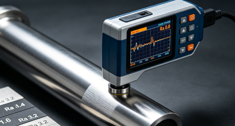
We use Mitutoyo portable contact profilometers. We can export printed inspection reports with Ra readings attached to every batch of parts for aerospace, medical and automotive quality audits.
Does climb milling produce a better Ra than conventional milling?
Absolutely. Climb milling reduces cutter rubbing and material tear, delivering 30–50% smoother surface roughness on all finishing passes.
Closing Paragraph
Stable Ra surface finish is not down to operator luck.
It comes from following written ISO/ASME standards, locking cutting parameters, managing tool wear, and separating roughing from finishing passes strictly.
When you set clear, graded Ra values on your drawing, you get consistent part quality and avoid paying for unnecessary ultra-fine machining.
If you need stable, batch-to-batch controlled surface roughness on CNC milled metal and plastic parts, send your STEP files to Zorapid today.
We will lock your Ra specs in our production workflow and provide full profilometer inspection reports on request.
Zorapid | Precision CNC Milling with Controlled Ra Surface Finish


